

Ijraset Journal For Research in Applied Science and Engineering Technology
Modelling, Analysis and Fabrication of CNC Crankshaft for Single Cylinder for 100CC Four-Stroke Engine
Authors: T. Niranjan, P.Ramsai Diwakar Babu, Vadthya Sevya, Sai Prasad Reddy, Santhosh Kumar
DOI Link: https://doi.org/10.22214/ijraset.2024.66085
Certificate: View Certificate
Abstract
This paper presents an integrated methodology for the development of an advanced crankshaft, incorporating SolidWorks for modelling, ANSYS for analysis, and CNC milling for manufacturing. SolidWorks facilitates the exploration of innovative design parameters, including material selection and stress analysis, while ANSYS ensures comprehensive structural and dynamic analyses. The optimized design is seamlessly translated into the manufacturing phase, utilizing CNC milling technology for precision machining operations. The CNC milling process, guided by the SolidWorks model, ensures exceptional dimensional accuracy and surface finish, contributing to the production of a high-performance crankshaft. This work further includes a modification phase, informed by insights from ANSYS analyses, aimed at strategically enhancing the crankshaft\'s mechanical properties. Rigorous testing validates structural integrity and overall functionality. This integrated approach offers a synergistic solution for engineers and manufacturers, showcasing the seamless collaboration between design, analysis, and manufacturing. The outcomes contribute to the advancement of crankshaft technology, providing a blueprint for optimizing engine performance through a holistic and technologically advanced approach.
Introduction
I. INTRODUCTION
Majority of steel crankshaft failure occurs due to fatigue failure, which may originate at the change of cross-section such as at the lip of oil hole bored in the crankpin. Vibration is one of the cause of failure of crankshaft. If the engine is running with heavy vibration especially torsional vibration, it may lead to crack in the crankpin and journal. One of the reason to fail the crankshaft due to insufficient lubricant. If the lubrication of bearing in the crankshaft is starved, it may lead to wipe out of the bearing and failure of the crankshaft takes place.
FEA modelling and analysis of crankshafts was performed by [1-3] and their study focused on fatigue performance evaluation and comparisons of forged steel and ductile cast iron crankshafts. In their study[4-6], crankshaft specifications, operation conditions, and various failure sources are discussed. The literature [7-10] included a review of the effect of influential parameters such as residual stress on fatigue behavior and methods of inducing compressive residual stress in crankshafts. The common crankshaft material and manufacturing process technologies in use were compared with regards to their durability performance. This was followed by a discussion of durability assessment procedures used for crankshafts, as well as bench testing and experimental techniques. In their literature review, geometry optimization of crankshafts, cost analysis and potential cost saving opportunities are also briefly discussed.
In this work, material and manufacturing processes of crankshafts are discussed. This study is focused mostly about structural load analysis, finite element modeling and optimization. Here it is verified the problem obtaining in the crank, the main reason is to sustain the heavier and sudden loads on the body and even the main larger shaft which is joined to the smaller shaft which is used to rotate the crank. So here the main load should be analyzed and necessary changes should be done to improve the sustainability.
II. FEA MODELLING and ANALYSIS
The objective of the present work is To design the crankshaft by using standard mathematical design procedure. First, a three-dimensional model of crankshaft is created by using Solid works software as per calculations. To run FEA analysis on designed crankshaft by considering engine gas combustion load and torque parameters by using ANSYS Workbench software to evaluate the total deformation, von-misses stress, and maximum principal stress.
The main source of forces applied to a crankshaft is the product of combustion pressure which is acting on the piston top. This kind of huge force exerted onto a crankshaft rod journal which produces substantial torsional and bending moments and the resulting shear, compressive and tensile stresses. Hence, we need to considered all these parameters and design the crankshaft accordingly. 3D View of Conventional Model and modified model of crank shaft is shown in Fig.1.Stress distribution and deformation of the conventional and modified model Modified model are shown in Fig.2 and Fig.3.
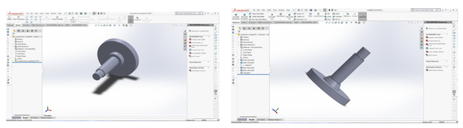
Fig. 1 3D View of Conventional Model and Modified Model
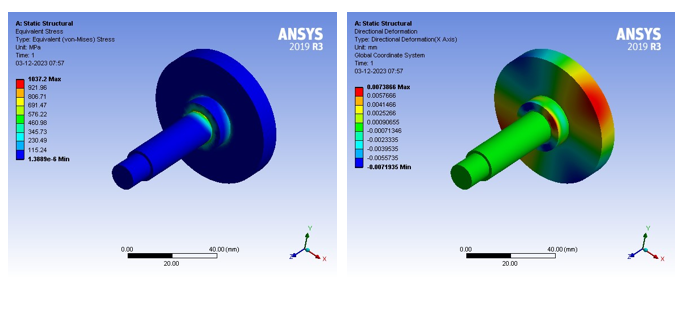
Fig.2 variation of stress and directional deformation for the conventional model
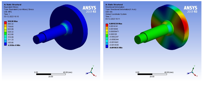
Fig.3 variation of stress and directional deformation for the modified model
III. EXPERIMENTATION
CNC milling, synonymous with machining, employs rotational tools to shape materials on a machine bed. Systems typically feature 3 linear axes (X, Y, Z), with advanced ones having 5 degrees of freedom (A, B) for intricate geometric complexities. The process involves translating a CAD model into machine instructions (G-code), cutting a block of material, aligning it accurately, and utilizing high-speed tools for material removal, achieving final part precision in multiple passes. The crank shaft manufactured using CNC milling is as shown in Fig. 4.Stress and deformation graph for the convenction crank shaft and modified crank shaft are shown in the Fig.5.
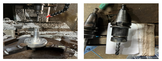
Figure 4 modified component manufactured and Tool bit used for process in CNC using Al 6061
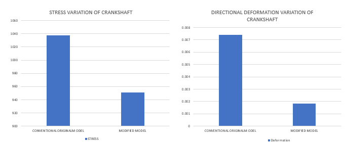
Figure 5 Graph for Stress and Directional deformation
Conclusion
As if we verify the results obtained here the Ansys results obtained in the ANSYS software, here from the graphical comparison we can see that the stress is very less in modified model using Al6061, but when we compare the deformation results here also modified model using Al6061 obtained the better when compared with conventional model. And after verifying the remaining results of strain and directional deformation we can conclude that the Al 6061 using modified model can be used for the better results. Manufacturing process has also done with the obtained results. Further work can be carried out using ANOVA and Taguchi’s Analysis for analysing the effect of process parameters [11-13]. Also, optimization of process parameters can be studied using metaheuristic algorithms [14-16].
References
[1] Mange, Mahesh, Suhas Uthale, and Richa Agrawal. \"Investigation and Optimization of two cylinder crankshaft by FE Analysis.\" International Research Journal of Engineering and Technology (IRJET) 3 (2016): 1541-1545. [2] Gadge, Lakhan, K. K. Gadgey, and Sunil Jamra. \"Finite Element Analysis of Two Wheeler Honda Bike Crank Shaft.\" International Journal of New Technology and Research 4, no. 5 (2018): 263061. [3] Dindore, Aniket, and Ganesh Badiger. \"Optimization of crankshaft by modification in design and material.\" Int Res J Eng Technol 7, no. 3 (2020): 3321-3325. [4] Shenkar, Sujata Satish, and Nagraj Biradar. \"Design and Static Structural Analysis of Crankshaft.\" International Journal of Scientific Engineering and Technology Research (IJSETR), ISSN (2015): 2319-8885. [5] Shahane, V. C., and R. S. Pawar. \"Optimization of the crankshaft using finite element analysis approach.\" Automotive and Engine Technology 2 (2017): 1-23. [6] Sandya, K., M. Keerthi, and K. Srinivas. \"Modeling and stress analysis of crankshaft using FEM package Ansys.\" International Research Journal of Engineering and Technology (IRJET) 3, no. 1 (2016): 687-693. [7] Cihan, Ömer. \"Deformation and stress analysis of crankshafts for single cylinder and four cylinder ic engine using ansys.\" Cumhuriyet Science Journal 41, no. 1 (2020): 298-304. [8] Hameed, Md, Chova Deekshith, Gorge Bhanu Prasad, and Chalamala Teja. \"Design and Analysis of Crankshaft for Internal Combustion Engine.\" Published in International Journal of Trend in Scientific Research and Development (ijtsrd), ISSN (2019): 2456-6470. [9] Bist, Himanshu, and Himanshu Bhatt. \"Modeling and Analysis of Crankshaft (Using ANSYS).\" International Journal of Recent Engineering Science 8, no. 2 (2021): 1-9. [10] Harshada, Dhekale, Jagtap Ashwini, Lomte Madhura, and Yadav Priyanka. \"Design, Analysis & Optimization of Crankshaft Using CAE.\" IPASJ International Journal of Mechanical Engineering (IIJME) 4, no. 4 (2016): 33-38. [11] Niranjan, T., Singaravel B, Chakradhar Band Senthil Kumar D., Investigation of vegetable oil as dielectric fluid in electric discharge machining, Materials Today: Proceedings, 2023 [12] Niranjan, T., Singaravel, B., Chakradhar, B., & Raju, S. S. (2023). Process parameter optimization in friction stir welding process using Taguchi method. Materials Today: Proceedings. [13] Niranjan, T., B. Singaravel, S. Srinivasulu Raju, Jakkana Aditya Ram, and K. Shamhith Reddy. \"Experimental Study on Effect of Process Characteristics during Electronic Discharge Machining of Titanium Alloy Using Multi Hole Tool Electrode.\" Advanced Materials Research 1178 (2023): 15-21. [14] Niranjan, T., Thanigaivelan, R., & Singaravel, B. (2022). Analysis of a Multi-channel Closed Loop Green Supply Chain Using Modified Particle Swarm Optimization Algorithm. In Innovations in Mechanical Engineering: Select Proceedings of ICIME 2021 (pp. 797-807). Singapore: Springer Nature Singapore. [15] Niranjan, T., & Parthiban, P. (2019). Modelling and analysing an integrated multi channel food supply chain distribution of an Indian dairy firm using modified TLBO algorithm. [16] Niranjan, T., B. Singaravel, and S. Srinivasulu Raju. \"Integrated fuzzy criteria evaluation with metaheuristic optimization for green supplier selection and order allocation.\" In IOP Conference Series: Materials Science and Engineering, vol. 1057, no. 1, p. 012074. IOP Publishing, 2021.
Copyright
Copyright © 2024 T. Niranjan, P.Ramsai Diwakar Babu, Vadthya Sevya, Sai Prasad Reddy, Santhosh Kumar. This is an open access article distributed under the Creative Commons Attribution License, which permits unrestricted use, distribution, and reproduction in any medium, provided the original work is properly cited.

Download Paper
Paper Id : IJRASET66085
Publish Date : 2024-12-23
ISSN : 2321-9653
Publisher Name : IJRASET
DOI Link : Click Here
 Submit Paper Online