Ijraset Journal For Research in Applied Science and Engineering Technology
- Home / Ijraset
- On This Page
- Abstract
- Introduction
- Conclusion
- References
- Copyright
Optimization of Motion Planning for Quadrotor-Equipped Robotic Manipulators
Authors: Melwin Tony V, Perarasu P, Dr. Anbarasi MP
DOI Link: https://doi.org/10.22214/ijraset.2024.64601
Certificate: View Certificate
Abstract
The focus of the work is on optimizing motion planning for quadcopter-equipped robotic manipulators by integrating quadcopter design, modeling, and path planning for a robotic arm mounted on a quadcopter through MATLAB. Recently, quadcopters have also been used in many application fields with increased viability. This paper will attempt at bringing a complete framework that enhances the operational capabilities of quadcopters through optimized path planning algorithms. The approach will rely on obstacle avoidance techniques for safe operation with satisfactory efficiency in unstructured environments. Advanced algorithms such as Rapidly-exploring Random Trees and dynamic window approaches provide solutions to this challenge of redundancy in the path followed and adaptability in its surroundings. Simulations prove that the proposed optimization methods strongly improve the accuracy and efficiency of the path planned by the robotic arm as it adheres to the dynamic constraints imposed. This work can apply practical insight into many real-world fields such as logistics, surveillance, and search-and-rescue applications aside from contributing to the theoretical understanding of quadcopter dynamics.
Introduction
I. INTRODUCTION
Quadrotors are a type of unmanned aerial vehicle (UAV) that uses four rotors to achieve lift and control. They have gained popularity due to their ability to perform vertical take-off and landing (VTOL), hover in place, and execute agile maneuvers. Quadrotors are differentially flat systems, meaning their states and inputs can be parameterized by a finite number of variables and their derivatives. This property simplifies control and trajectory planning. Robotic manipulators are mechanical devices consisting of a series of links connected by joints. They are designed to perform physical manipulation tasks such as lifting, moving, and placing objects in various industrial environments.
A quadrotor can also be defined as a floating base system. A floating base system is a robot structure that can freely move through space in three dimensions. As a result, the base can move in two ways (translation and rotation). This means the base is a six DOF (degrees of freedom). The quadrotor is a flying vehicle with a base that can freely translate and rotate in space. The quadrotor's base is often represented as a rigid body with a "floating" joint that connects to the "world" frame, which allows the quadrotor to move around and rotate freely. The "floating" characteristic of the quadrotor base is to be attributed to the aerial manipulation, where a robotic arm is attached to it, for example. Formulating quadrotors as floating base systems allows for an accurate representation of their dynamics and enables the development of advanced control strategies and motion planning algorithms to address their complicated behavior. Floating-base robots can freely translate and rotate in space with six degrees of freedom.[1]
The integration of quadrotors and robotic manipulators has been an active area of research in recent years. This combination of an aerial vehicle like a quadrotor with a robotic manipulator attached underneath is commonly known as aerial manipulators, which allows for manipulation tasks in environments that are difficult to access or hazardous for humans. Aerial manipulation systems have garnered significant attention recently, which enable quadrotors to interact with objects beyond their physical envelope. Their potential applications, including package delivery, inspection, and servicing in hard-to-reach areas like high-altitude towers, bridges, and rooftops, have sparked interest. However, the highly dexterous nature of these systems and the complex dynamics of the aerial vehicle-manipulator interaction pose substantial challenges in planning and control problem.[2] In this paper, an optimized path planning of the quadrotor attached with a robotic manipulator is simulated and other optimization techniques for better motion control are presented. The literature searches on optimized path planning of manipulators present a new collision avoidance method for a multi-jointed robot in 3D space. The approach unifies route planning with real-time adaptation to moving obstacles during its motion. These techniques have been demonstrated through simulations to minimize motor accelerations by up to 90% and joint speed/acceleration by 50%/80%. That makes the robots much safer and more efficient for practical use. This mechanism allows robots to quickly adapt to changing environments.[3]
The robot manipulator has to be brought to an optimum motion. Optimal motion planning of such a system would ensure an effective motion. Here, the path from the start to the goal should be optimum and handle the minimum requirement of such variables as distance, time, or energy. Optimization techniques in determining the optimal trajectories are presented in existing literatures. The pursuit of optimal trajectories involves Genetic Algorithms, mainly for the task of obstacle avoidance. Supporting the other types of solutions that might improve performance, the paper supports the flow of robots in ways that ensure security and efficient motion.[4]
Aerial manipulators that consist of a hexacopter and a two-degree-of-freedom robotic arm are controlled by an augmented adaptive sliding mode controller based on a closed-chain robot dynamics. A motion planning algorithm is proposed by exploiting rapidly exploring random tree star (RRT*) and dynamic movement primitives (DMPs). During aerial transportation, to avoid unknown obstacle, DMPs modify the trajectory based on the virtual leader–follower structure. By the combination of RRT* and DMPs, the cooperative aerial manipulators can carry a common object to keep reducing the interaction force between multiple robots while avoiding an obstacle in the unstructured environment.[5]
II. SYSTEM DESIGN
The architecture of a quadcopter-equipped robotic manipulator typically consists of the following key components:
A. Quadcopter Platform
The quadcopter serves as the base for the robotic manipulator, providing mobility and the ability to access hard-to-reach areas. It typically has four rotors arranged in a symmetrical configuration to enable stable flight and precise control. The quadcopter includes a flight controller, motors, electronic speed controllers (ESCs), and a power source (battery).
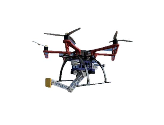
Fig.1 Design of UAV equipped with the manipulator [6]
B. Robotic Manipulator
The robotic manipulator is attached to the underside of the quadcopter, allowing it to interact with the environment and perform tasks. It consists of a series of links connected by joints, which provide the necessary degrees of freedom for manipulation. The manipulator can have varying numbers of joints and configurations, such as a serial or parallel structure, depending on the specific application requirements. Actuators, such as servomotors or stepper motors, are used to drive the joints and control the manipulator's movements.
C. Integration and Control
The quadcopter and robotic manipulator are integrated through a mechanical interface, ensuring a secure and stable connection. A central control system coordinates the operation of both the quadcopter and the manipulator, processing sensor data and generating control commands. Sensors, such as inertial measurement units (IMUs), GPS, and cameras, provide feedback on the system's state and the environment, enabling autonomous or semi-autonomous operation. Communication between the control system and the quadcopter/manipulator is typically achieved through wired or wireless connections, depending on the specific implementation.
A power source, usually a battery, supplies electricity to both the quadcopter and the robotic manipulator. The power system is designed to provide sufficient energy for the desired mission duration, considering the power requirements of all components. Power management and distribution circuits ensure efficient and safe operation of the integrated system.
By combining the capabilities of a quadcopter and a robotic manipulator, this architecture enables a versatile aerial manipulation system capable of performing tasks in hard-to-reach areas, such as inspection, maintenance, and object manipulation.
III. MODELING
To simulate the behavior of the actual system or design controllers, the modeling of rigid body systems must be accurate. Beyond a certain number of bodies, solving this problem with conventional methods such as using Euler-Lagrange equations or the Newton-Euler method becomes more and more difficult. The modeling is done by integrating tools from Lie group theory and matrix exponentials. This method becomes possible if we use Lie group representation. Observing the problem systematically, we have only to add more rigid bodies like the free-floating basis. The need to establish link frames is what brings the complexity in modeling of mechanical systems like kinematic chains. Lie group theory and matrix exponentials enable the reduction of this complexity, leading to a limited number of frames with just a single inertial fixed frame needed. The exponentials formula is used to find the kinematics. The fundamental idea behind this formula is to treat the motion of each joint as a screw motion.
Figure 2 shows the coordinate frames for the manipulator-equipped quadcopter system. Let Fi, Fb, and Fc be the inertial frame, the body ?xed frame of the multirotor, and the end-effector frame of the robotic arm, respectively. Fb is located at the center of the quadrotor.[7]
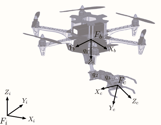
Fig.2 Coordinate Frames of the system
The aerial manipulator system is modeled in the general configuration as shown in the figure 3.
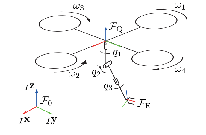
Fig.3 General Forces and Torques acting on the system.
Initially, the configuration is calculated by assuming that the initial position configuration in the reference frame is known. The chosen minimal coordinates are

consist of the position (x, y, z), the roll, pitch and yaw angle (
 , θ, ψ) and the manipulator joint angles (q1, q2, q3). The first derivative results in
which gives us the following equation.
 (1)
(1)
The generalized quasi-velocities of the system are defined as

Where 
 represents the configuration of the base relative to its body fixed twist. Since
 may not be a suitable or desired part of the quasi-velocity vector of the system a change of coordinates must be applied. This can be done by finding a transformation


 (2)
(2)
where 
 =
= 
 and
and 
 is the desired vector of the quasi-velocities that are still to be chosen. By using the chain rule, the relationship.

 (3)
(3)
with the matrices


The equations of motion of any system is generally given by,
 (4)
(4)
Here for this system of aerial manipulator, the equation of motion can be derived, where the matrices can be written by


Here 
 and
and 
 are the mass and Coriolis matrix of the overall system regarded as a rigid body.
 describes the momentum cross-coupling of the kinematic chain and the base body,
 denotes the generalized Forces that result from the external applied forces,
 denotes the generalized forces that result from the gravitational forces acting on the rigid bodies.
The non-holonomic quasi velocities

 (5)
(5)
are chosen to be the angular and translational velocities resolved in quadcopter fixed frame 
 and the joint velocities of the manipulator (
 ).
).
With the rotation matrix
 (6)
(6)

 (7)
(7)
A coordinate transformation matrix from 
 to
to 
 is given as H(q)

 (8)
(8)
The relationship can be expressed as

 (9)
(9)
As a final step the twist of the quadcopter has to be expressed in terms of 
 as stated in (2). This can be achieved by the matrix,

 (10)
(10)
By applying the coordinate transformation as in (3) the equations of motion of the overall system are found. To simplify the equation of motion, the mass matrix is partitioned

 (q) =
(q) = 

With 
 calculated as in (3). The matrix
 is a constant and diagonal matrix and given as

with the mass of body i noted as 
 . In a similar manner the Coriolis matrix is partitioned


with 
 also calculated as in (3). The generalized forces of the system are described as

with the input vector 
 . Here ki is some function of the rotational speed of the propellers
 . Mi denotes the torques applied to the joints of the manipulator.
In the following representation the underactuated nature of the overall system is revealed since there are no entries in x and y direction. This means that the behaviour of the system cannot be affected directly. In order to move the system has to roll or pitch and as a result a motion in x or y direction is observed. [8]
- SIMULATION
The simulation for path planning of the aerial manipulator was carried out in the MATLAB software. The simulation environment was created in MATLAB, utilizing the Robotics System Toolbox. It included a virtual representation of the workspace with various obstacles to mimic real-world conditions. A grid or occupancy map was employed to define the layout of the environment, allowing for efficient path planning.[9]
As the system of quadrotor UAV with a robotic arm mounted to it is considered as a floating-base system, path planning is modeled by collision-free geometric paths for floating-base systems using the "floating" type rigidBodyJoint and manipulatorRRT functions in MATLAB. To start with initially an empty rigid body tree and a rigid body are created with a floating joint. Then the geometry of the quadrotor is imported into MATLAB as a triangulation object from the design as shown in Figure 4.
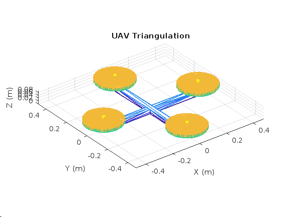
Fig.4 UAV Triangulation
Then the UAV rigid body is added to the floating-base rigid body tree and the robotic arm rigid body tree model is mounted to the UAV floating base and the UAV with the mounted arm is visualized as in Figure 5. The motion planning problem is to find a collision-free path from a starting joint configuration to a desired goal configuration. The aspects to be determined initially to find the motion planning include: Starting joint configuration, Goal joint configuration, UAV collision model, Obstacles in the environment, and Robot's Kinematic Constraints.
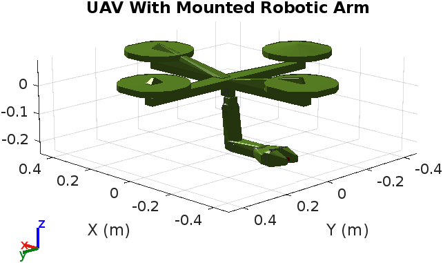
Fig.5 Rigid body model of the system
The simulation environment is created using collision boxes and the positions of the boxes are set such that they create a wall between the start and goal configurations as shown in Figure 6. Then a collision-free path is formulated between the start and goal joint configuration using manipulatorRRT to plan a geometric collision-free path.
V. RESULTS
The path planning algorithm is used by the manipulatorRRT object in MATLAB which is a single-query planner for manipulator arms that uses the bidirectional rapidly exploring random trees (RRT) algorithm with an optional connect heuristic to potentially increase speed.
The bidirectional RRT planner creates two trees with root nodes at the specified start and goal configurations. To extend each tree, the planner generates a random configuration and, if valid, takes a step from the nearest node. After each extension, the planner tries to connect the two trees accomplished with the new extension and the closest node on the opposite tree. Invalid configurations or connections that collide with the environment are not added to the tree. The random number generator is seeded and using RRT, a path is planned which is then shortened and interpolated to make it smoother.
The planned geometric path of the system is animated and the trajectory is observed as seen in Figures 6 and 7.
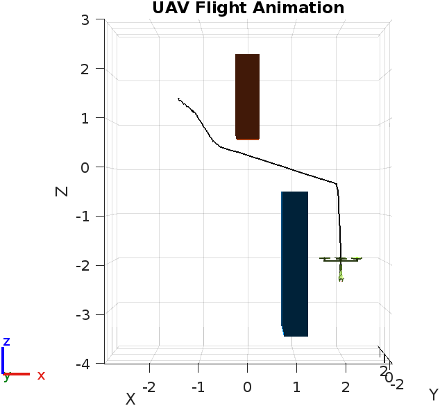
Fig.6 Planned Path Trajectory (view 1)
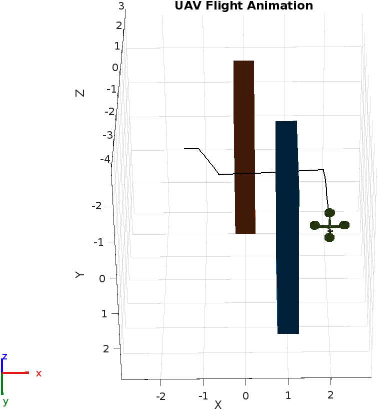
Fig.7 Planned Path Trajectory (view 2)
Note that the arm also moves along the path to avoid colliding with the obstacles in the environment. The joint angles of the robotic arm in the planned path are plotted in Figure 8. Based on the path planned by the RRT algorithm the joint angles tend to vary, providing a suitable collision-free optimized solution.
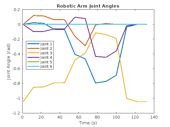
Fig. 8. Joint Angles
The results from the path planning experiments demonstrate several key aspects of the motion planning process. The implementation successfully creates a collision-free geometric path for the quadrotor and its attached robotic arm. By thoroughly analyzing the joint angles throughout the planned trajectory, you can ensure the robotic arm is operating safely and effectively while mounted on the quadrotor, paving the way for successful real-world deployment in applications such as inspection, maintenance, and manipulation tasks.
With increasing investment in the development of autonomous systems in different fields, improving the skills of quadrotors in dynamic conditions will be important. This detail indicates that future work might involve using sensors and coupling them with quadrotor control so that they can dynamically navigate around unplanned obstacles. Similarly, different trajectory optimization techniques might be posed such as genetic algorithms or reinforcement learning in order to maximize the performance of the trajectory. In addition, the multi-quadrotor-robotic systems coordination strategies for multi-agent systems remain a captivating area of exploration subject to accomplishing cooperative missions in dynamic environments such as the rescue or building processes. Task-based optimization techniques for performance improvement, in particular execution time and precision, can be employed in the case of inspection or manipulation applications.
Conclusion
This research work successfully applied an optimized motion planning framework in quadrotor equipped robotic manipulators through applying enhanced algorithms for the efficient creation and execution of trajectories. For this purpose, the manipulatorRRT algorithm was employed to achieve obstacle avoidance considering both the quadrotor and engineered arm’s motion capabilities. The obtained results demonstrate significant improvements in the accuracy of performed maneuvers, time affordable for their implementation and the arithmetic stability of trajectories’ execution. The posed motion planning concept was validated by measuring the angles of the robotic manipulator joints during the implemented trajectories of the robotic arm and was able to keep all the moving elements within the designated angles without any collision with obstacles. These observations bring new possibilities of using optimization methods developed by us in practice and promote the progress in the fields of logistics, search and rescue as well as industrial automation.
References
[1] The MathWorks, Inc., (2024) \"Inverse Kinematics for Robots with Floating Base - MathWorks.\" [Online]. Available: https://in.mathworks.com/help/robotics/ug/ [2] Soham S Patkar, \"Motion Planning for Aerial Manipulation in Constrained Environments,\" M. Sci. thesis, The Johns Hopkins University, Baltimore, Maryland, May, 2018 [3] Palmieri G, Scoccia C. Motion Planning and Control of Redundant Manipulators for Dynamical Obstacle Avoidance. Machines. 2021; 9(6):121. [4] ATA, Atef. (2007). OPTIMAL TRAJECTORY PLANNING OF MANIPULATORS: A REVIEW. Journal of Engineering Science and Technology. 2. [5] H. Lee, H. Kim and H. J. Kim, \"Planning and Control for Collision-Free Cooperative Aerial Transportation,\" in IEEE Transactions on Automation Science and Engineering, vol. 15, no. 1, pp. 189-201, Jan. 2018. [6] AlAkhras A, Sattar IH, Alvi M, Qanbar MW, Jaradat MA, Alkaddour M. The Design of a Lightweight Cable Aerial Manipulator with a CoG Compensation Mechanism for Construction Inspection Purposes. Applied Sciences. 2022; 12(3):1173. [7] Seo, Hoseong & Kim, Suseong. (2017). Aerial grasping of cylindrical object using visual servoing based on stochastic model predictive control. 6362-6368. 10.1109/ICRA.2017.7989751. [8] Martin Schabetsberger, Univ.-Prof. Dr.-Ing. habil. Andreas Müller, DI Gabriel Krög. 2022. \"Modelling and Control of a Quadcopter Equipped with a Manipulator Arm\", Master’s thesis, Johannes Kepler University Linz, Österreich, 2022. [9] The MathWorks, Inc., (2024) \"Plan Path of Robotic Arm Mounted on Quadrotor - MathWorks.\" [Online]. Available: https://in.mathworks.com/help/robotics/ug/ [10] Sinnemann, J., Boshoff, M., Dyrska, R. et al. Systematic literature review of applications and usage potentials for the combination of unmanned aerial vehicles and mobile robot manipulators in production systems. Prod. Eng. Res. Devel. 16, 579–596 (2022).
Copyright
Copyright © 2024 Melwin Tony V, Perarasu P, Dr. Anbarasi MP. This is an open access article distributed under the Creative Commons Attribution License, which permits unrestricted use, distribution, and reproduction in any medium, provided the original work is properly cited.

Download Paper
Paper Id : IJRASET64601
Publish Date : 2024-10-15
ISSN : 2321-9653
Publisher Name : IJRASET
DOI Link : Click Here
 Submit Paper Online

