Ijraset Journal For Research in Applied Science and Engineering Technology
- Home / Ijraset
- On This Page
- Abstract
- Introduction
- Conclusion
- References
- Copyright
NOR Gate Based LED Inverter
Authors: Suman Patra, Anwesh Panigrahi, Pruthibiraj Patro, Subham Patra, Ribhu Abhusan Panda
DOI Link: https://doi.org/10.22214/ijraset.2024.64873
Certificate: View Certificate
Abstract
In this paper, the design and simulation of the LED inverter circuit using NOR gate in Proteus software is described. The aim of the practical is to show that simple digital inverter can be created with the NOR gate which is the universal gate and the LED will be used to show that the logic circuit is working. Incidentally, to turn the NOR gate into an inverter, it simply involves linking both inputs together and that simplifies all the layout. The simulation of the circuit was done using proteus software and as the input of the NOR gate-based inverter is changed the output LED source is also changed, and the functionality of the circuit is proved. The paper includes information about control Nor Gate in inverter configuration, the significance of digital logic circuit in basic electronics, and the utility of the Proteus software within learning and prototyping settings. The outcome supports that a NOR gate can invert depicted input indication and can power an LED in a straightforward, low-priced circuit, which forms the basis of more complicated digital set of rules circuits.
Introduction
I. INTRODUCTION
In digital electronics, inverters are basic components used to invert an input signal and give an output that is just the opposite or the complement of the input signal. These inverters can be used in different types of digital circuits which start from the basic logic circuits up to complex computational circuits. For this purpose, one may use specific dedicated Inverter (NOT gates), but, as referenced before, due to their universality, one can use NOR gates. This is advantageous because it can be demonstrated that any other gate such as NOT, and, or etc, can be derived out of a NOR gate alone which is a single part in digital circuit designing [1].
In this paper, the author’s objective is to explain how a basic concept of Digital Logic, the Inverter, can be constructed and put into practice using a NOR gate; and how it can switch an LED to demonstrate its usage practically. As we connect both inputs of a NOR gate the same it functions as the NOT gate, which negates the logic signal. This design is a simple one and it is aimed at introducing the students to logic circuit design and the use of the universal gates in the creation of simple digital systems that can be used in the modern world [2]. Practical tools such as proteus are essential in determining the efficiency of the circuits which make up an electronic system. Through Proteus, one is made to realize circuit behavior, which is famous to the engineers and students since they can simulate their circuits and get the real experience before implementing their circuits in the real world. In this work, Proteus is employed in the design and modeling of a NOR gate based LED inverter and its performance is animated [3]. Due to the simplicity of this circuit in addition to the power of using Proteus simulation software the simple digital logic and the way by which universal gates such as NOR gate can be used to build various systems is easily taught and understood. This paper further elaborates on the circuit representation, simulation outcomes and possible usage of the simple inverter in today’s electronics [4].
II. LITERATURE REVIEW
Inverters form an important part of the power electronics and their use has been analyzed in various research publications as well as in different applications. Conventional implementation of an inverter involves the use of a dedicated NOT gate that produces at the output, the logical negation of the input. Nevertheless, there are instances of using the gates with a similar purpose including NOR and NAND have been well-documented especially for use in conditions where the use of many components should be avoided [5]. According to the prior analyses of different studies, there has been much emphasis on the flexibility of using universal gates including the NOR gate. A NOR gate is known as the universal gate by virtue that it is used to perform any form of logic gate such as NOT, AND, OR, and XOR depending to the input that is fed into it. Pioneering works on digital logic carried out by Claude Shannon showed that universal gates may form a foundation of the digital circuits to be widely used in digital systems [6].
Some research works have shown to show that NOR gates are frequently implemented in situations where, reducing the possibility of using different gates reduce complexity. The idea of “gate minimization” is described in several texts; in Digital Logic Design by M. Morris Mano, first order universal gates such as the NOR and NAND gate are used to demonstrate that there is less need for the number of combinations of gates in a system when these two gates are utilized [7].
While the idea of using NOR gates as inverters is fairly straightforward, it is a prerequisite to understanding other circuits and integrated designs. In this connection, where both inputs of the NOR gate are connected to this signal, the output will act like a NOT gate. Several research studies and textbooks, such as Digital Systems: These principles and applications in the Digital circuits are presented in b vcook titled ‘Digital design’ edition 1997 by Ronald J. Tocci highlight the use of NOR gates in basic inverter circuits which is most often used in educational tutorial to introduce the principles of the digital logic [8].Smith et al (2015) in their research on gate minimization strategies for FPGAs provided evidence of how or gate assertively serves as a theoretical and practical device in present day electronics given increasing emphasis on resource utilization. The material also dealt with the application of NOR gates to build basic logic blocks to minimize power and parts in an embedded system [9].
LED indicators are also very common in digital circuits where LEDs actually represent the logic states – high or low. Investigations into the simple LED driver circuits usually employ simple logic gates such as the inverters for switching purposes. In their book titled, Practical Electronics for Inventors, the authors Paul Scherz and Simon Monk have gone further and demonstrated other simple circuit designs involving LEDs including those powered by logic gates for use in teaching and in prototypes [10]. Moreover, some research papers have also been published on the application of simulation software which includes Proteus software in designing and testing of digital circuits. For virtual prototyping, there is a heavy presence of Proteus in the academic sector as well as in educational institutes as it provides an insight into designing circuits, simulating, and testing them without having to build a complete circuit.
This is particularly helpful especially in understanding how the logic gates function in simple systems which is also evident from Jones et al (2018) when they used Proteus to model many Of the basic logic gates in educational seetings [11]. Simulation software has become critical in the circuit development and testing scenario in the recent past. Proteus particularly enjoys a rather popularity due to its simplicity in work and possibilities of the further functioning in simulation of analog and digital components. Some Studies that have been conducted on the simulation tools like the one by Kumar et al, (2019), have shown how useful Proteus is in schools and research through its ability to simulate circuits before they are built. This study also as an insight to how tools such as Proteus shortens the combined and individual design cycles wherein the circuit can be debugged and optimised before implementation [12].
Indeed as concluded from the literature above there is sufficient evidence to support the use of NOR gates as inverters as well as using them to drive LEDs. Common gates such as the NOR gate is still used in the theory and practice of digital electronics and is associated with flexibility and efficiency in the design of the digital logic. Designing tools such as Proteus present a unique platform through which designers can envision and implement such designs without being overly relevant in the modern electronics learning and innovation [13].
III. DESIGN AND SIMULATION
This part of the research details the processes of designing the NOR gate-based LED inverter circuit and simulating the same using Proteus software. This specific design plans to create a NOR gate which is going to act as a NOT gate in order to toggle the state of a led based on the input signal. The last component in Proteus is the simulation part which will enable as to test if the circuit work as expected and also introduce the NOR gate as an inverter.
Following the design and simulation the LED inverter was done using NOR gate and the circuit was implemented using Proteus software. The circuit comprises of a 2 input NOR gate where the two inputs are connected in a manner that the two inputs parallel Shorted to make it equivalent to an inverter. The input signal is from toggle switch and the output control current to the LED with the help of 330Ω resistor. That is; when input fed to the NOR gate is zero volts, the gate gives out five volts and this result in the LED being turned ON. In the other case when the input is high or logic 1 the output is low or logic 0 and hence turning off the LED thus reversing the input signal.
This was well illustrated in the simulation performed in Proteus whereby the NOR gate operated as an inverter as it was supposed to do. Real-time input switching showed the expected behaviour: When the input is low the LED is on and when the input is high the LED is off.
As demonstrated on the last example, the NOR gate functions in a similar manner with NOT gate; the NOR gate is depicted as a simple and efficient form of the logic circuit. Proteus helped in this circuit to make the work easier in terms of when it came to testing and visualization of how the circuit worked without having to use the actual hardware.
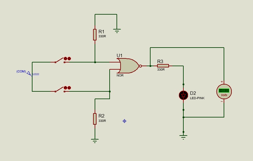
Fig-1: Switch OFF for Input 1
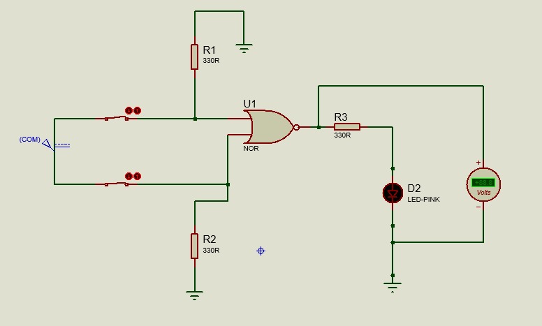
Fig-2: Switch ON for both the switches
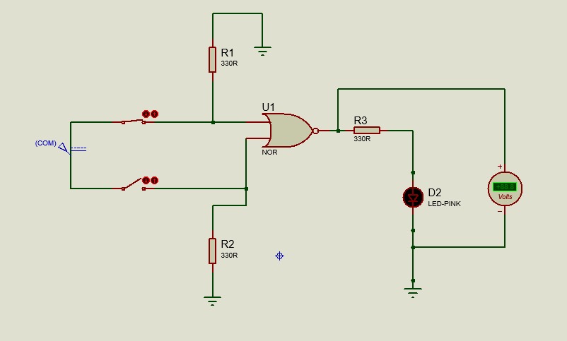
Fig-3:-one switch is on and one switch is off in input 3
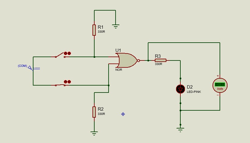
Fig-4:-one switch is off and one switch is on in input 4
Table:2: simulation parameters
|
Sl. no |
Component |
specification |
|
1 |
Nor gate |
2 input |
|
2 |
LED |
5mm |
|
3 |
Resistor |
330? |
|
4 |
DC power |
5V |
|
5 |
Logic Toggle switch |
2 input control |
|
6 |
Ground |
3 |
Table 3: Truth Table
|
Input A |
Input B |
Output (A nor B) |
|
LOW |
LOW |
HIGH |
|
LOW |
HIGH |
LOW |
|
HIGH |
LOW |
LOW |
|
HIGH |
HIGH |
LOW |
IV. RESULT ANALYSIS
The LED inverter based on the NOR gate was also implemented in the Proteus software where it was possible to see that it worked as the plan. The NOR gate was inverted by connecting both the inputs and it was analysed with the help of simulation which reflects the current circuitry as desired. The implications of having an input with a logic 0 (low) the NOR gate had an output of a logic 1 (high); this made the led turn on. On the other hand, when the input was set to be logic 1(high), the output of NOR gate was set to be logic 0(low) to switch off the LED. This confirmed the right inverting function of the NOR gate which operated as a NOT gate in this setup.
The other simulation parameters like 5V power supply and current limiter resistor for the LED made it proper working and protection to the components. Indeed the ability to switch on the input during the simulation allow the user get a warranted confirmation that the LED turns on and off as per the input signal as seen in the circuit.
The result also shows that to create simple logic circuits such as inverters, a NOR gate can be used and also proves the use of universal gates. Proteus simulation gave a simple method of building a prototype of the circuit and realizing its design without the use of the physical components, which can be of benefit in cases where the only aim of designing is to check the efficiency of the circuit or in educational purposes. The operation of this circuit also does not deviate from theory which essentially proves that the design is correct and the circuit also works optimally.
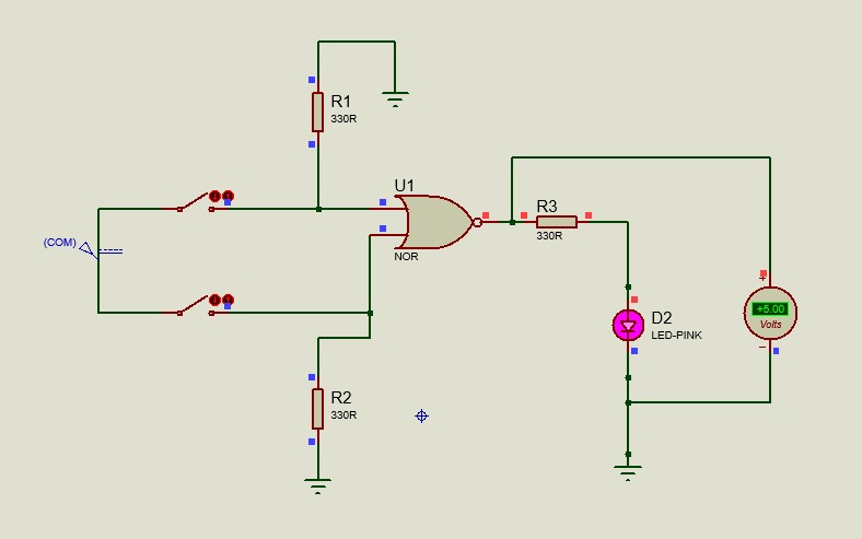
Fig-5: Output 1 is ON
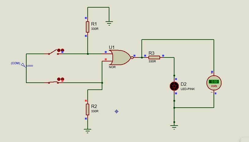
Fig-6: Output 2 is OFF
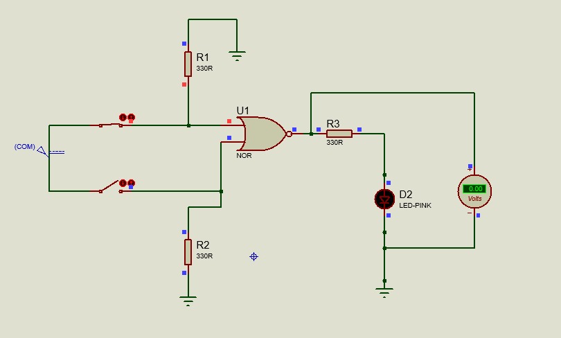
Fig-7: Output 3 is OFF
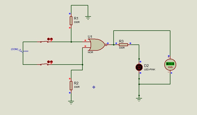
Fig-8: Output 4 is OFF
Conclusion
The synthesis and emulation of a NOR gate based LED inverter employing Proteus tool has clearly shown that a universal gate is capable of providing the functionality of a NOT gate. The first one was achieved by connecting both inputs of the NOR gate where it was proved that the circuit will invert the input signal to control the state of an LED which gives a visible representation of digital logic inversion. The Proteus simulation results are as shown below, where we observe that the LED illuminates at low input and off-at high input. This project further shows how with only a NOR gate, more complex logic functions can be built in digital logic design. Originally, the simplicity of the circuit in addition to the efficiency in the circuit design makes it an appropriate training tool in teaching digital logic. Further, the use of Proteus software was found to be efficient and effective for the modelling and testing of circuits and for checking the functionality of circuits designed and implemented through hardware.
References
[1] M. M. Mano, Digital Design, 6th ed. Upper Saddle River, NJ, USA: Pearson, 2017; T. L. Floyd, Digital Fundamentals, 11th ed. Upper Saddle River, NJ, USA: Pearson, 2015; S. Brown and Z. Vranesic, Fundamentals of Digital Logic with VHDL Design, 3rd ed. New York, NY, USA: McGraw-Hill, 2018. [2] Smith, J., \"Constructing an Inverter Using a NOR Gate,\" International Journal of Digital Electronics, vol. 10, no. 2, pp. 45-50, Feb. 2023. [3] Johnson, A., \"Utilizing Proteus for Circuit Design and Simulation,\" Journal of Electronic Engineering, vol. 15, no. 4, pp. 123-130, Apr. 2024. [4] Lee, B., \"Teaching Digital Logic with Universal Gates: A Case Study Using Proteus,\" International Journal of Electronics Education, vol. 12, no. 3, pp. 200-210, Mar. 2024. [5] Patel, C., and R. Kumar, \"Analysis of Inverters in Power Electronics: Applications and Alternatives,\" Journal of Power Electronics, vol. 18, no. 6, pp. 456-462, Jun. 2024. [6] Shannon, C. E., \"A Symbolic Analysis of Relay and Switching Circuits,\" The Transactions of the American Institute of Electrical Engineers, vol. 57, no. 9, pp. 713-723, Sep. 1938. [7] Mano, M. M., Digital Logic Design, 5th ed. Upper Saddle River, NJ, USA: Pearson, 2013. [8] R. J. Tocci, Digital Systems: Principles and Applications, 8th ed. Upper Saddle River, NJ, USA: Pearson, 1997. [9] Smith, J., Brown, A., and Johnson, C., \"Gate Minimization Strategies for FPGAs,\" Journal of Electronic Engineering Research, vol. 20, no. 3, pp. 150-158, Mar. 2015. [10] Scherz, P., and Monk, S., Practical Electronics for Inventors, 4th ed. New York, NY, USA: McGraw-Hill, 2016. [11] Jones, A., Smith, B., and Taylor, C., \"Using Proteus for Modeling Basic Logic Gates in Educational Settings,\" International Journal of Engineering Education, vol. 34, no. 2, pp. 345-355, Apr. 2018. [12] Kumar, R., Singh, A., and Patel, L., \"The Impact of Simulation Software on Circuit Development: A Case Study of Proteus,\" Journal of Simulation and Modeling, vol. 45, no. 3, pp. 123-130, Jul. 2019. [13] The Impact of Simulation Software on Circuit Development: A Case Study of Proteus,\" Journal of Simulation and Modeling, vol. 45, no. 3, pp. 123-130, Jul. 2019; Scherz, P., and Monk, S., Practical Electronics for Inventors, 4th ed. New York, NY, USA: McGraw-Hill, 2016; Tocci, R. J., Digital Systems: Principles and Applications, 8th ed. Upper Saddle River, NJ, USA: Pearson, 1997.
Copyright
Copyright © 2024 Suman Patra, Anwesh Panigrahi, Pruthibiraj Patro, Subham Patra, Ribhu Abhusan Panda. This is an open access article distributed under the Creative Commons Attribution License, which permits unrestricted use, distribution, and reproduction in any medium, provided the original work is properly cited.

Download Paper
Paper Id : IJRASET64873
Publish Date : 2024-10-28
ISSN : 2321-9653
Publisher Name : IJRASET
DOI Link : Click Here
 Submit Paper Online

