Ijraset Journal For Research in Applied Science and Engineering Technology
- Home / Ijraset
- On This Page
- Abstract
- Introduction
- Conclusion
- References
- Copyright
A Novel Affordable Assistive Mobility Aid for the Visually Impaired
Authors: Aryan Deswal
DOI Link: https://doi.org/10.22214/ijraset.2024.65333
Certificate: View Certificate
Abstract
Of the 8 billion people alive today, over a billion suffer from some level of vision impairment, with 43 million being fully blind. This paper focuses on the millions of people who lack access to affordable assistive devices. Most visually impaired individuals, particularly those in low- and middle-income regions, rely on traditional aids like canes due to the high cost and limited availability of alternative solutions. The paper presents a field-tested, cost-effective and inconspicuous assistive mobility device designed to aid visually impaired individuals in navigating their surroundings safely. The device employs an ultrasonic sensor, microcontroller, rechargeable battery, and buzzer to detect obstacles within a specific range and provide auditory alerts to the user. Through rigorous lab testing and real-world validation, the device’s effectiveness in detecting obstacles and guiding users was demonstrated. Its affordability, simplicity, and inconspicuous design make it a promising solution for enhancing the mobility and independence of visually impaired individuals worldwide. Future upgrades aim to extend the device\'s operational time, reduce its size, and implement voice recommendations based on detected obstacles.
Introduction
I. INTRODUCTION
According to the International Agency for the Prevention of Blindness, 1.1 billion people are living with vision loss as of 2020. Out of this, 43 million are blind and another 295 million have moderate to severe visual impairment [1]. A WHO report further states that the distant vision impairment is four times higher in middle income regions than in high income ones [2]. According to another study in 2015, 89% of visually impaired people live in low- and middle income countries. 62% of the visually impaired world population lives in three Asian regions: South Asia (73 million), East Asia (59 million) and Southeast Asia (24 million) [3]. A large percentage of these people are unable to benefit from modern assistive technology due to its high cost, complexity in design, extensive training requirements (combined with language or translation problems), and inadequate reach. Thus, they are forced to use the ancient walking stick, or get assistance from others for navigation. There is thus a need for development of inconspicuous, affordable, and safe assistive devices which can substitute or complement existing systems to assist visually impaired people, especially those living in low- and middle-income regions.
II. MOTIVATION
Current work in assistive devices for visually impaired individuals, such as the Smart Cane and other innovations, reflects a growing interest in improving navigation and obstacle detection (we discuss such related work in detail in the next section). However, despite the effective integration of sensors and devices, significant challenges persist. Many systems depend on huge predefined datasets, undermining adaptability to unforeseen scenarios. Issues like interference in RFID technology deployment, reliance on specific mobile platforms, and potential vulnerabilities in Bluetooth connectivity have been identified.
Additionally, current solutions are expensive, complex, and known to be hard to integrate for real world users. Research in the Global North often overlooks the economic constraints faced by potential users, limiting accessibility for low-income individuals, or those who are less educated. In fact, blindness is much more likely to occur in disadvantaged populations who do not have access to advanced medical care at a young age [4]. As such, there is a compelling need to explore and develop assistive technologies that not only address technical limitations but also prioritize cost-effectiveness, simplicity in design, and seamless integration (with a focus on marginalized populations). This ensures availability and affordability for a broader spectrum of users, highlighting the importance of creating inclusive solutions for the visually impaired community.
III. RELATED WORK
The literature on assistive devices for the visually impaired reveals a collective effort to enhance navigation and obstacle detection through electronic aids. These devices leverage various technologies, such as laser scanners, camera sensors, or sonar, to collect environmental data and provide information through tactile or auditory feedback.
Nivedita et al. presented the Smart Cane, showcasing effective obstacle detection and object recognition through the integration of a Raspberry Pi 3 as the central controller [5]. Tapu et al. present the Computer Vision System (ComVis Sys), a real-time obstacle detection system attached to a smartphone for autonomous mobility [6]. However, challenges arise from its reliance on a predefined image dataset, limiting adaptability in unforeseen scenarios.
Kher et al. presented The Intelligent Walking Stick for the Blind, incorporating infrared sensors, RFID technology, and Android devices for improved navigation [7]. Similarly Saaid et al. present the Radio Frequency Identification Walking Stick (RFIWS) for sidewalk navigation, utilizing RFID technology to calculate distance from the sidewalk border [8]. Challenges include the deployment of RFID technology, susceptibility to disruptions and potential vulnerabilities of Android and Bluetooth connectivity.
Wahab et al. explore the development of another Smart Cane, a portable device equipped with ultrasonic sensors, microcontroller, vibrator, buzzer, and water detector. Fonseca et al. 's Electronic Long Cane (ELC) uses ultrasonic sensors and micro-motor actuator delivering tactile feedback using haptics technology [9].
Cognitive Aid System for Blind People (CASBlip), proposed by Dunai et al., provides a wearable aid system combining sensor and acoustic modules for object detection and navigation. This design incorporates 3D Complementary Metal Oxide Semiconductor (CMOS) image sensors and laser light beams delivering environmental information through stereophonic headphones [10].
IV. LIMITATIONS OF CURRENT WORK
The existing literature demonstrates diverse approaches to assistive devices, each with unique strengths and limitations. Despite their capabilities, none of these devices could become popular, especially in low- and medium-income regions of the world. It can be deduced that while addressing challenges in navigation and obstacle detection for the visually impaired, there is a continual need for improvements in adaptability, cost-effectiveness, and seamless integration for wider accessibility. Some of the issues are discussed below.
A. High Cost
Some of the devices developed for assisting users include integration of GPS, Google Maps, iPads, Laser Detection and Ranging (LDR), cameras etc. Others included the generation of virtual reality through special kinds of glasses. While all such incorporations improved the capability of the device, they also increased the cost exponentially, and made it more conspicuous, causing the user to be too self-conscious in public. Few examples of such devices along with their costs are given below:-
WeWalk Ultrasonic Smart Cane pairs an assistive technology enabled cane handle with a graphite white cane. It costs $649.[11]
Ray Electronic Mobility Aid for the Blind is a handheld, lightweight and compact supplement to traditional canes for the blind. It costs $299.[12]
Biped is a harness worn on shoulders and has three wide angle cameras, a battery and a minicomputer. It detects obstacles in the 170 degree zone both by day and night. It costs €2950.[13]
Another assistive aid is a Guide Dog. However, they are not only prohibitively costly ($50000-$60000) but also have recurring expenditures. Not only is the cost price of these systems high, the recurring expenditures of such aids also make them non-viable for the majority of the population.
B. Complexity in Design
Some of the devices developed are very complex in design and require extensive training for the user. E.g.:
- The vOICe system, patented by Philips Co., converts visual depth information into an auditory representation [14]. This device successfully uses a camera as an input source and converts the image to sounds, where frequency and loudness represent the position, elevation and brightness. This requires extensive training and still overloads the user with unnecessary information. This limitation may compromise the basic requirement of avoiding obstacles.
- The Intelligent Glass (IG) system comprises a pair of stereo-cameras mounted on the glasses’ frame to acquire the environment in the direction of look, algorithms to identify the obstacles in the scene, their relative position and display of all this information on a tactile display for appreciation by the user. The tactile map presented to the user has an embossed representation of the obstacles’ locations [15].
Such systems require resources to not only buy such costly devices but also to pay for training. Providing such devices through social initiatives or government schemes is also difficult. Further, despite training, fully mastering their usage may take years.
C. Inappropriate Integration
Few devices are developed using ultrasonic sensors. These are either planned to be attached to the walking cane or be hand held. This makes the sensor’s look angle inclined by 30 to 45 degrees upwards from the direction of motion of the user. This look angle also keeps varying very haphazardly due to the movement of the stick or hand. Thus, the output of such devices is not only erratic and erroneous but may also result in missing obstacles which are right in front of the user and cause injuries.
D. Limitations of the Conventional Cane
Despite numerous efforts and a variety of wearable assistive devices available, user acceptance is usually quite low. The conventional cane continues to be the most commonly used device, especially in low- and medium-income regions of the world. It ranges from a simple wooden stick for the extremely poor demographic to a simple white cane for those who can afford it. A physical cane works like an extension of one’s arm to detect obstacles ahead. This is achieved by exploring the environment ahead by moving the cane at two different points, one to the left and another to the right, parallel to the direction of motion.
A conventional cane caters only for the Operational Zone and is of little value against obstacles outside it (note the Zone of Interest). This results in an individual directly getting hit by the obstacle (e.g., those protruding above the knee level like the branch of a tree) or a delayed avoidance when the obstacle has already entered the Operational Zone. This not only results in physical harm but also adversely affects self-confidence since the individual becomes too conspicuous.
It is always difficult to accept changes to the status quo. Adapting to a change requires motivation, a cost-benefit assessment and serious consideration of the extent of training requirements, affecting their willingness to try. Therefore, individuals from regions of low per capita income have shown indifference towards technologically advanced mobility assistive aids developed so far. Interactions with visually impaired people from these regions indicated their willingness to try a device which is affordable and does not require extensive training.
V. NEGOTIATING SURROUNDINGS
Humans sense their environment approximately 90% from two senses - sight (about 80%) and hearing (about 10%). The remaining 10% of information is acquired from smell, touch, and taste senses [16]. Thus, sight in particular is critical during the motion of an individual from one place to another. In the absence of visual input and any equipment, a blind person naturally extends their arms to feel any obstacles in an attempt to navigate. A cane is a natural tool: but can something better be done? To better understand the requirements of a visually impaired person and develop an appropriate aid, the area around an individual, in the direction of motion, is analyzed and divided in two zones. For the purpose of this study, these have been categorized as ‘Operational Zone’ and ‘Zone of Interest’. As shown in Fig. 1.
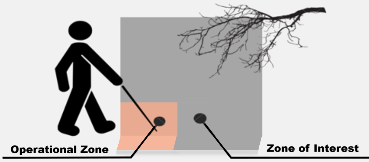
Fig. 1 Categorisation of Areas Around an Individual
A. Operational Zone
The Operational Zone is the area from immediate physical contact to the arm's reach. It is the space, in the direction of motion, where a blind person can easily detect and avoid an obstacle using their sense of touch, the white cane, or other tactile cues. Specifically, it refers to the space from the ground up to the knee level. Any undulation or obstruction in this zone may result in loss of balance of the individual and cause injury.
B. Zone of Interest
The Zone of Interest refers to areas beyond the immediate reach of a visually impaired person where one relies more on auditory cues. This can extend to any distance. However, for any realistic assessment and development of a suitable aid it is restricted to a distance of approximately seven feet or two meters. A suitable warning about any obstacle present in this zone, if generated at a distance of two meters, allows the user to prepare for or execute an action in navigating past such obstacles in a safe manner.
VI. DEVELOPMENT OF ASSISTIVE DEVICE
An assistive device was required which could provide auditory cues for obstacles in the Zone of Interest and thus aid users in negotiating their way forward with adequate anticipation and safety. Any such assistive device must meet the following requirements:
- The device should be affordable for people of low- and medium-income regions around the world.
- Should be lightweight, simple, and inconspicuous.
- Should be able to detect obstacles from ground level as well as above the waist.
- Should be able to generate an audible warning tone to alert the individual without startling the user, unlike vibrational stimuli.
VI. COMPONENTS OF ASSISTIVE DEVICE
Based on the requirements, a rechargeable mobility assistive device is developed which can detect obstacles in the Zone of Interest and produce an audible alert for the user. Basic components of such a system are an ultrasonic sensor, microcontroller, rechargeable battery and a sound producing device. A simple block diagram is given below:-
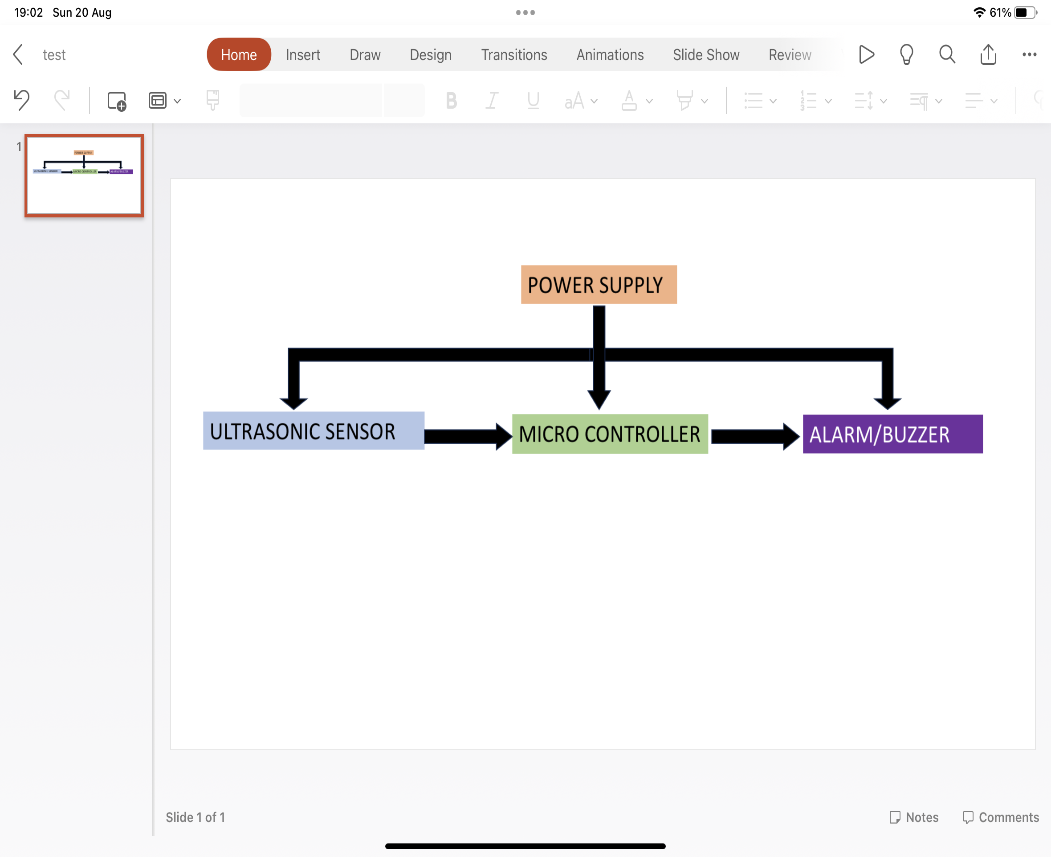
Fig. 2 Block Diagram of the Device
A. Power Supply
Power supply to the device is given by a 3.7 volt, 1500mAh rechargeable Lithium Polymer battery. A voltage step-up module increases the 3.7V to 5V, required for optimally powering the microcontroller, ultrasonic sensor and the buzzer. The battery can be recharged using a commonly available micro-USB cable. A single battery charge can last for 24 hours of operational use.
B. Ultrasonic Sensor
Ultrasonic sensors are devices that use sound waves with frequencies ranging from around 20 kHz to 200 kHz to detect objects and measure distances. A commonly used frequency is 40 kHz. The operating principle is based on emitting a sound wave (ultrasonic pulse) and measuring the time it takes for the wave to travel to and fro from the sensor to an object. Since the speed of sound in prevailing environment is known and the time taken for the wave to return can be recorded, the distance from the object can be calculated trivially using the formula:
Distance = (Speed of sound * Time taken)/2
The detection range within which an ultrasonic sensor can accurately detect objects can vary from a few centimeters to several meters, depending on the sensor model. The area covered at any particular range depends on the beam angle (which can vary from 15 to 60 degrees). A narrow beam is required for high precision, while a wider beam covers a larger area.
The device used here is HC-SR04. It consists of two ultrasonic transmitters (basically speakers), a receiver, and a control circuit. Operating at an input voltage of 5V, the sensor draws low current of up to 20mA at maximum load. Its digital output signals correspond to two voltage levels i.e., a high of 5 Volts and a low of 0 Volts, enabling easy integration into various electronic systems. The sensor's operational temperature range lies between -15°C and 70°C, making it suitable for diverse environmental conditions.

Fig. 3 Top and Bottom View of HV-SR04 Ultrasonic Sensor
The HC-SR04 employs the working principle in following manner: -
- The ultrasound transmitter (trigger pin) emits a high-frequency sound (40 kHz).
- The sound travels through the air. If it encounters an object, it gets reflected back to the module.
- The ultrasound receiver (echo pin) receives the reflected sound (echo).
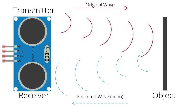
Fig. 4 Working Principle of Ultrasonic Sensor
C. Microcontroller
A microcontroller is a compact integrated circuit that contains a processor, memory, and input/output pins. All these components are on a single chip. The microcontroller consists of input and output pins which are used to receive and send out signals. The sensor outputs are fed into the input pins of the microcontroller. The microcontroller receives signals from the sensors, processes these signals and accordingly triggers the buzzer which produces an audible beep to warn the user of an approaching obstacle. The device uses ATmega8A high-performance, low-power Atmel 8-bit AVR RISC based microcontroller which combines In-System Programmable (ISP) Flash memory with read-while-write capabilities. It operates between 2.7-5.5 volts. [16]
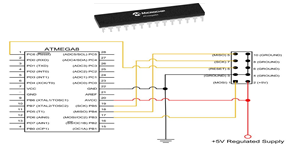
Fig. 4 ATMega8A Microcontroller and Breadboard Circuit
D. Buzzer
A buzzer is an electronic component used to generate audible sound signals or alerts in any device. It consists of an electromechanical transducer that converts electrical signals into sound waves. The device used here is a generic buzzer.
E. Device Case
Case for the prototype was developed using a standard 3-D printer. (Fig. 5)
The dimensions of the device’s case were guided by following criteria: -
- Overall device size was aimed to be inconspicuous to ensure that the user doesn’t feel uncomfortable while carrying the device.
- Should be lightweight.
- Should be able to accommodate all the components in a single case.
- Should be attachable to personal clothing without the requirement of any additional casing.
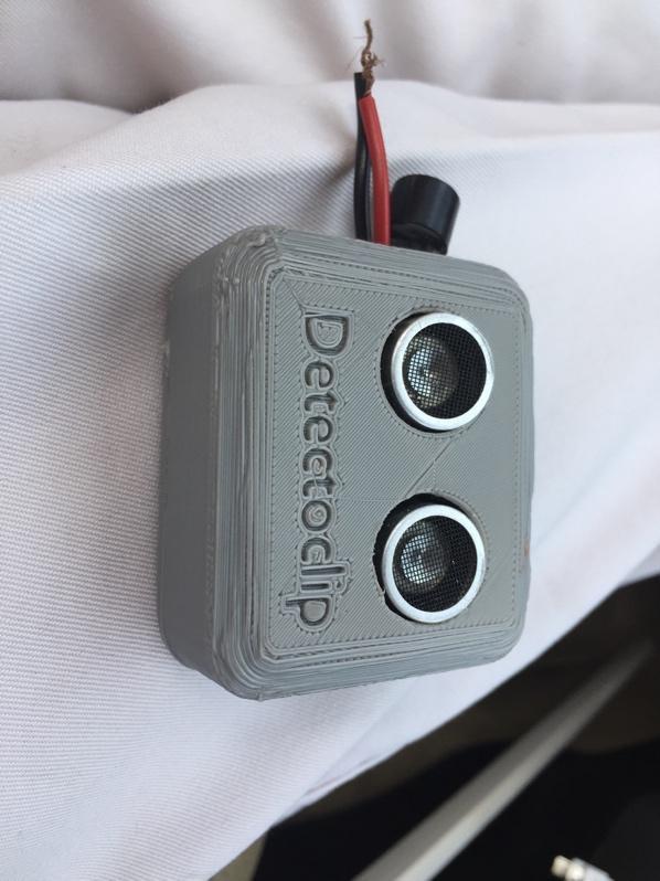
Fig. 5 Case for the Mobility Aid
VIII. DEVICE OPERATION AND VALIDATION
The device is designed for being clipped to a cap, shirt, belt or anywhere on the person. It can also be attached to the walking stick. The device was aimed at not only picking up stationary obstacles in the path of the user but also those that emerge suddenly in the path such as vehicles and other movable objects or beings, regardless of which direction they are moving in.
A. Operating Algorithm
The device follows a simple algorithm as described below- and depicted in Figure 6. When a visually impaired person moves forward, the device will sense any obstacle in one’s path. Once an obstacle is detected, the time between the sensor pulses is fed to the microcontroller, which uses the speed-distance formula to calculate the distance of the object. If said distance is above a predetermined limit, the signal is discarded. If the distance is below the limit, power is supplied to the buzzer, which gets activated. This alerts the user, who can then act to avoid the obstacle. Once action is taken, the buzzer will stop, and the system will continue monitoring and guiding the user.
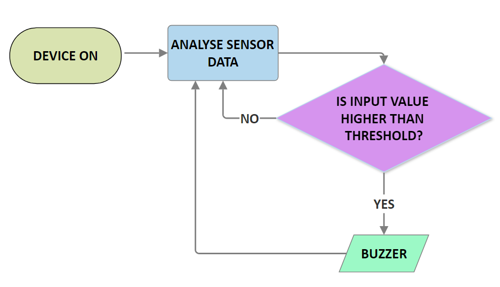
Fig. 6 Algorithm Used for Activation of Device’s Buzzer
B. Testing of Device
The device testing was carried out in two phases. First phase involved lab testing to validate the operations of the device as per the desired logic and to ensure production of auditory cues in a controlled environment. Second phase involved presenting the operations of the device to a sample population and validating its operation in a realistic environment through use by volunteers. For lab testing of the device the device’s detection threshold for activation of the buzzer was put at two meters.
1) Random Presentation of Obstacles in Lab: Obstacles were presented at different distances in the direction of motion of the device. This was to simulate obstacles that enter the field of view outside the look angle of the sensor, but closer to it than the distance threshold for activation. It was observed that the device picked up these obstacles on every occasion and the buzzer was activated whenever the distance of the obstacle was less than two meters as programmed in the device. The test results are as tabulated in Table 1.
|
Distance (in Meters) of activation of Buzzer |
Test No. |
|
2.005 |
1 |
|
1.997 |
2 |
|
1.998 |
3 |
|
2.010 |
4 |
|
1.998 |
5 |
|
2.001 |
6 |
|
1.995 |
7 |
|
1.997 |
8 |
|
2.003 |
9 |
|
2.009 |
10 |
Table 1. Activation of Buzzer on Random Presentation of Obstacles
2) Progressive Reduction of Distance from Obstacles in Lab: Progressive reduction of distance between the device and existing obstacle in the direction of motion. (Simulating a visually impaired person proceeding towards an obstacle.) The test results show that the buzzer was activated on all occasions when the obstacle reached a distance range between 1.99 meters to 2.01 meters. The measurements for 10 such tests are given at Table 2.
|
Test No. |
Distance (in Meters) |
Buzzer Activation |
|
1 |
5.350 |
No |
|
2 |
1.521 |
Yes |
|
3 |
1.675 |
Yes |
|
4 |
6.238 |
No |
|
5 |
1.235 |
Yes |
|
6 |
1.945 |
Yes |
|
7 |
4.589 |
No |
|
8 |
2.852 |
No |
|
9 |
0.761 |
Yes |
|
10 |
5.739 |
No |
Table 2. Distance of Activation of Buzzer on Progressive Movement Towards Obstacle
3) Field Validation of Device: Post development and lab testing, the device was put up for field validation in a practical environment. Consent was taken from members of the Blind People’s Association, Ahmedabad. The device was pinned to the shirt pocket of the sample individual. The user, under supervision, was asked to move around an area cluttered with vehicles, people, trees, flowerpots etc. All movements were conducted without any restrictions on environmental sound or other activity. It was clearly demonstrated that the individual was able to navigate his way through the environment [18].
IX. FUTURE PROSPECTS
Future plan involves three major aspects. These are:-
1) Technical upgrades. This would include:
- Larger battery capacity giving the device an extended operational time.
- Allow charging by USB-C cables.
- Further reduce the dimensions to make it slimmer and more inconspicuous.
- Implement voice recommendations based on distance and type of obstacles.
- Integration of other sensors based on requirements.
2) Establishing the supply chain for distribution. This would involve initial engagement with NGOs and government bodies to ensure the requisite funding and utilization of their network for distribution of the device to the most affected regions.
3) The present device is a step towards seamless integration of sensors, maps and technology all around us so that vision impairment is not as big an impediment as it is today. The device, in the future, can be upgraded to provide data, with user consent, to work for broader accessibility goals. These may include but not limited to:-
4) Studying the mobility pattern with respect to time of the day to contribute to larger studies.
5) Linking to auto opening of doors/ boom barriers in residential apartments or office complexes.
Conclusion
The paper starts by noting the failure of modern assistive technology for real-world visually-impaired users. Our analysis reveals the cost, complexity, and requirement of extensive training are some of the core reasons for the rejection of modern assistive aids by people from low- and medium-income regions. We design, implement, and field-test a new solution: an aid that is affordable, user-friendly, and inconspicuous. Various tests carried in lab environments as well as its validation in real-world scenarios prove its effectiveness. The device was appreciated and praised by individuals who has previously been exposed to other modern aids, which were designed to be attached to the cane and vibrate on detecting any obstacles. The plan now is to give the device to a larger sample for usage and collection of data for future upgrades without compromising on the basic requirement of it being inconspicuous and affordable to the majority of visually impaired people of low- and medium income regions of the world.
References
[1] Bourne R, Steinmetz J, Flaxman S, et al., Trends in Prevalence of Blindness and Distance and Near Vision Impairment over 30 years: an analysis for the Global Burden Of Disease Study, Lancet Glob Health, 2020. Accessed via the IAPB Vision Atlas. Available: (https://www.iapb.org/learn/vision-atlas) [2] (2023) World Health Organisation Website. Available: https://www.who.int/news-room/fact-sheets/detail/blindness-and-visual-impairment [3] Bourne RRA, Flaxman SR, Braithwaite T, Cicinelli MV, Das A, Jost B. et al., Magnitude, temporal trends and projections of the global prevalence of blindness and distance and near vision impairment: a systematic review and meta-analysis. Lancet 2017;5(9): e888—e897. [4] Flaxman, Seth R et al. “Global causes of blindness and distance vision impairment 1990-2020: a systematic review and meta-analysis.” The Lancet. Global health vol. 5,12 (2017): e1221-e1234. doi:10.1016/S2214-109X(17)30393-5. Available: https://pubmed.ncbi.nlm.nih.gov/29032195/ [5] D S, Muktha & Gokulmuthu, Niveditha & Pinto, Nikhil & Sinha, Somnath. (2024). Enhancing Mobility: A Smart Cane with Integrated Navigation System and Voice-Assisted Guidance for the Visually Impaired. 1124-1129. 10.1109/CSNT60213.2024.10546111. [6] Tapu, Ruxandra & Mocanu, Bogdan & Zaharia, Titus. (2013). A computer vision system that ensures the autonomous navigation of blind people. 1-4. 10.1109/EHB.2013.6707267. [7] Kher Chaitrali S., Dabhade Yogita A., Kadam Snehal K., Dhamdhere Swati D., Deshpande Aarti V, “An Intelligent Walking Stick for the Blind “, International Journal of Engineering Research and General Science Volume 3, Issue 1, January-February, 2015. [8] Saaid, Mohammad Farid & Ismail, Izwani & Noor, M.Z.H.. (2009). Radio Frequency Identification Walking Stick (RFIWS): A device for the blind. Proceedings of 2009 5th International Colloquium on Signal Processing and Its Applications, CSPA 2009. 250 - 253. 10.1109/CSPA.2009.5069227. [9] Abd Wahab, Mohd Helmy & Talib, Amirul & Abdul Kadir, Herdawatie & Johari, Ayob & Ahmad, Noraziah & Sidek, Roslina & Abdul Mutalib, Ariffin. (2011). Smart Cane: Assistive Cane for Visually-impaired People. CoRR. abs/1110.5156. [10] Dunai, Larisa & Defez, B. & Lengua, Ismael & Peris-Fajarnés, Guillermo. (2012). 3D CMOS sensor based acoustic object detection and navigation system for blind people. IECON Proceedings (Industrial Electronics Conference). 4208-4215. 10.1109/IECON.2012.6389214. [11] (2023) Independent Living Aids website. Available: (https://independentliving.com/wewalk-ultrasonic-smart-cane/) [12] (2023) Maxiaids website. Available: (https://www.maxiaids.com/product/ray-electronic-mobility-aid-for-the-blind) [13] (2024) Biped.ai website. Available: (https://biped.ai/#) [14] P. B. L. Meijer, \"An experimental system for auditory image representations,\" in IEEE Transactions on Biomedical Engineering, vol. 39, no. 2, pp. 112-121, Feb. 1992, doi: 10.1109/10.121642. [15] Velazquez R, Fontaine E, and Pissaloux E (2006) Coding the environment in tactile maps for real-time guidance of the visually impaired. In: Proc. of IEEE International Symposium on Micro-NanoMechatronics and Human Science, Nagoya, Japan. [16] Man, Dariusz & Olchawa, Ryszard. (2018). The Possibilities of Using BCI Technology in Biomedical Engineering. 10.1007/978-3-319-75025-5_4. [17] (2023) Microchip AtMega8A megaAVR Data sheet. Available: https://ww1.microchip.com/downloads/en/DeviceDoc/ATmega8A-Data-Sheet-DS40001974B.pdf [18] ‘Field Validation of Detectoclip’. Available: https://drive.google.com/file/d/1i-cAUTsq57EY-AtDT_Lr6n6BwOgYKapx/view?usp=drivesdk
Copyright
Copyright © 2024 Aryan Deswal. This is an open access article distributed under the Creative Commons Attribution License, which permits unrestricted use, distribution, and reproduction in any medium, provided the original work is properly cited.

Download Paper
Paper Id : IJRASET65333
Publish Date : 2024-11-17
ISSN : 2321-9653
Publisher Name : IJRASET
DOI Link : Click Here
 Submit Paper Online

