Ijraset Journal For Research in Applied Science and Engineering Technology
- Home / Ijraset
- On This Page
- Abstract
- Introduction
- Conclusion
- References
- Copyright
Numerical Analysis of Steel Frame Using Electro-Mechanical Impedance Technique
Authors: Laxmi Bhalla, Abhishek Mishra, Sachin Kumar Singh
DOI Link: https://doi.org/10.22214/ijraset.2024.64843
Certificate: View Certificate
Abstract
Nowadays, piezoelectric materials are most widely used in structural health monitoring (SHM) system for non-destructive evaluation. In this paper the damage study using electro-mechanical impedance (EMI) technique, which is non-destructive method of SHM. This paper presents a numerical analysis of four-story steel frame and multiple damages were induced in the steel frame by utilizing smart material like Lead Zirconate Titanate (PZT). A PZT-4 piezoelectric material was embedded in the beam of the frame. The type of damping used in steel frame model was Rayleigh damping. The numerical analysis was done in COMSOL MULTIPHYSICS 6.2 and frequency domain analysis was done, from that admittance values were find out for 30-300KHz frequency range. The real part of the admittance gives conductance values. Then, conductance verses frequency graph was created that will indicate the structural health and performance. Moreover, root mean square deviation (RMSD) index was found out for each case that provides a quantitative measure of deviation.
Introduction
I. INTRODUCTION
The electro-mechanical impedance technique is based on the principle of direct piezoelectric effect utilizing piezoelectric material [1-2]. It is a cost-effective method for SHM and for non-destructive evaluation for different types of engineering structures. SHM is a technique that deals with inspection and detection of damage of the structural system [3-5]. Therefore, SHM is important for scientists, all types of researchers in various disciplines. In EMI technique, smart material like PZT patch is embedded to the model to find out the structural health, it generally detects the variations occur in the structure, the PZT-patch works in high frequency range of 30KHz to 400KHz. Various studies were done on electro-mechanical impedance techniques as in [6-8]. Generally, non-destructive tests are time-taking, require bigger-size equipment that is why smart materials become more popular, also they have large frequency response range [9]. The static analysis of PZT actuator was done using finite element tool i.e. comsol [10]. Smart materials like lead zirconate titanate are very sensitive in detecting the damage in structural system it generally converts mechanical energy into electrical energy [11]. The admittance is the electrical response that we get by PZT-patch which consists of conductance and susceptance, where as conductance is real part and susceptance is an imaginary part [12]. The quantitative measurement of damage is generally measured in terms of damage index, two widely use damage indices are- root mean square deviation and correlation coefficient deviation metric [13-14]. The type of damping used in this paper was Rayleigh damping, the discretized matrix equation for finite element model under forced vibration can be represented as
[M]X? + [C]? + [K]X = F(t) (1)
Where, M, C and K are square matrices of N×N for structural mass, Rayleigh damping and stiffness respectively. Rayleigh damping can be expressed as
[C]= α[M] + β[K] (2)
Whereas α is constant mass matrix multiplier and β is constant stiffness matrix multiplier both values depend upon the modal damping (ξr) that can be expressed as
ξr= α2ωr + βωr2 (3)
Whereas ωr is the damping resonance frequency. Generally, for piezoelectric vibration α is assumed to be 0 by researchers for viscous damping. But under harmonic excitation β can be expressed as
β = 2ξrωr (4)
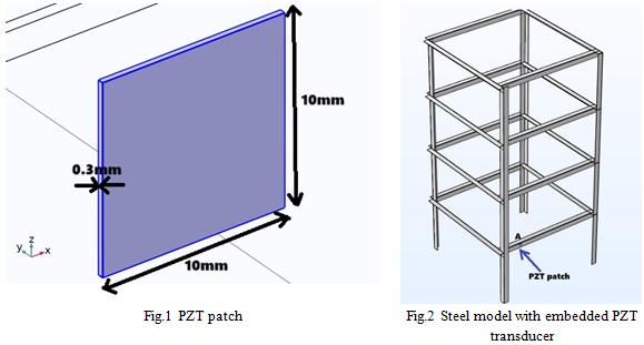
Using third equation, α and β can be easily determined for viscous damping or Rayleigh damping [15]. This paper deals with the four-storey steel frame structure, in which PZT-4 sensor was embedded as shown in fig.1. The dimension of the PZT patch was 10×10×0.3 mm3 . Multiple damages were induced in the beam which will discuss in this paper and type of finite element analysis software used was COMSOL MULTIPHYSICS 6.2.
II. METHODOLOGY
A four-story steel structure was modelled in FEA software named as COMSOL MULTIPHYSICS 6.2 and EMI technique was used to find out the signature of the beam damage in the steel model. A PZT-4 patch was embedded in the four- storey steel model. All properties of materials were assigned like modulus of elasticity, Poisson’s ratio, density of material etc. The boundary conditions were applied in 4-story steel frame and tetrahedral meshing was done in steel frame model. Frequency domain analysis was done to find out the admittance value for particular frequency range that varies from 30KHz to 300KHz. All members were connected by L-shape angles, there was four number of columns in the steel model. The L-angles has size of 24.4mm×2mm. The length of the column was 1100mm, the length of the front, rear beams were 530mm and the length of left, right-side beams were 550mm and the height of each floor was 275mm.
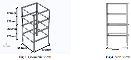
The isometric view of the four-story steel model is shown in fig.3 in which height of each floor was 275mm. The side view of the steel frame is shown in fig.4 in which left and right-side length of the beam was 550mm. The top view of the steel frame is shown in fig.5 in which the size of angle was 24.4mm×2mm.
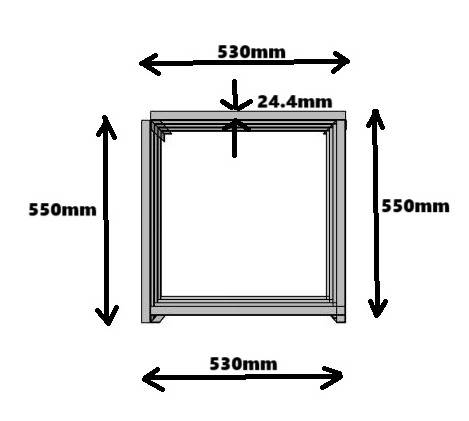
Fig.5 Top view
TABLE I
PHYSICAL PROPERTIES OF STEEL FRAME
|
Physical Properties |
Parameter |
Values(mm) |
|
|
Length |
1100 |
|
Column dimension |
Width |
24.4 |
|
|
Thickness |
2 |
|
|
Length |
530 |
|
Front and back beam’s dimension |
Width |
24.4 |
|
|
Thickness |
2 |
|
|
Length |
550 |
|
Left and right-side beam’s dimension |
Width |
24.4 |
|
|
Thickness |
2 |
TABLE II
PROPERTY OF STRUCTURAL STEEL
|
Unit |
Values |
|
|
Modulus of elasticity |
GPa |
180 |
|
Density of structural steel |
Kgm3 |
7850 |
|
Poisson’s ratio |
- |
0.3 |
TABLE III
PROPERTY OF PZT-4 PATCH
|
Parameter |
Value |
Unit |
|
Density of PZT material |
7500 |
Kgm3 |
|
Poisson’s ratio |
0.3 |
- |
TABLE IV
RAYLEIGH DAMPING PARAMETERS VALUE
|
Parameter |
Value |
Unit |
|
Damping type |
Rayleigh damping |
- |
|
Input parameters |
Alpha and beta |
- |
|
Mass damping parameter |
0 |
1/s |
|
Stiffness damping parameter |
3E-9 |
s |
Parameters to be considered in modelling involved in the analysis of four-story steel frame model which was modelled in COMSOL MULTIPHYSICS are as followed-
A. Geometry and dimension
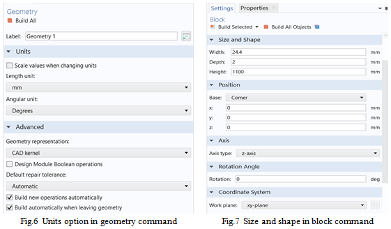
In COMSOL MUTIPHYSICS a four-story steel frame model was made, the all components of the model like beams, columns etc were made by using “block” command which was available in the “geometry” tab. First of all, the dimensions were set like length in mm and angular unit in degree as shown in fig.6. Then, after that the length, width, height of the block was mentioned as shown in fig.7. There were some other parameters that involved in this like position of base, axis type, work plane, rotation angle whose values were also assigned by clicking on the build all objects option. The whole model was prepared in the same way as the single block was made. After making the all blocks of the model “form union” command was used to make the structure as a whole structure.
B. Material Properties
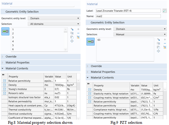
The material properties were defined to all the structural components like beams, columns of steel model. The properties were defined by using option “add material”. In “add material” command go to the “built-in” then “select structural steel” then after that select the all domains as shown in fig.8. and PZT selection shown in fig.9.
C. Boundary conditions
The boundary conditions were assigned to make steel frame as a fixed frame from the bottom. So, the commonly used fixed type of supports were used in steel frame. For this, go to the “solid mechanics” then go to the “fixed constraints” and then do boundary selection manually as shown in fig.10.
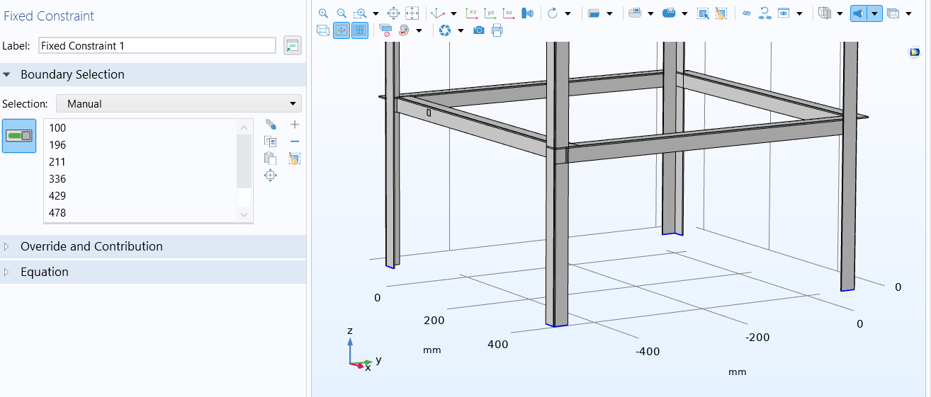
Fig.10 Fixed ends at the bottom of frame shown
D. Meshing
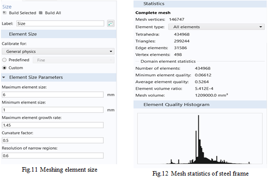
The meshing was done in the whole steel structure by go to the “mesh” then calibrate for “general physics” and select size then choose “custom” option and define element size parameter as shown in fig.11. The select the type of mesh as “free tetrahedral”.
E. Analysis Output
After assigning all parameters we move towards the “study” option and select the type of study as “frequency domain”. The unit of eigen frequency was selected as KHz. Then choose the range of frequency from 30 to 300KHz at interval of 10, then click on “compute” as shown in fig.13.
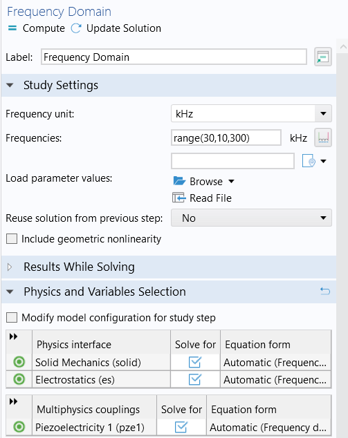
Fig.13 Computation of frequency domain
IIII. DAMAGE STUDY
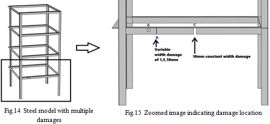
In the four-story steel model, the damage was done on the front side of the beam whose length was 530mm at height of 275mm. In all types of damages, the length and thickness of the damage was same except the width of the damage. The length and thickness of the damage were 24.4mm and 2mm. At point “C”, there was a damage of constant width of 10mm at distance of 265mm from corner of x axis in all cases as shown in fig. 15. At point “B” there were variable width damage of 1mm, 5mm and 10mm at distance of 132.5mm from corner of x axis. The PZT patch was embedded at point “A” which was at 100mm distance from corner of x axis as shown in fig.15. The dimension of PZT patch was 10×10×0.3mm3. The three cases of damage were-
Case 1 damage: 10mm at mid and 1 mm at one-fourth distance
Case 2 damage: 10mm at mid and 5 mm at one-fourth distance
Case 3 damage: 10mm at mid and 10 mm at one-fourth distance
IV. RESULT AND DISCUSSION
After the frequency domain analysis, the probe table of admittance and frequency was generated in the COMSOL MULTIPHYSICS 6.2 software, in which the frequency was varying from 30KHz to 300KHz. In admittance the real part denotes the conductance and an imaginary part denotes the susceptance. Here, we need only real part of the admittance which is conductance. From that we made conductance verses frequency graph which is known as signature of the damage steel frame model.
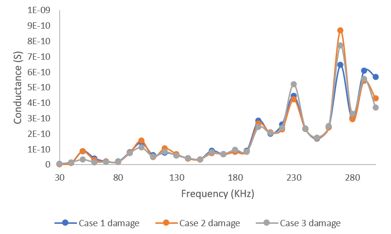
Fig.16 Conductance response obtained for frequency range of 30-300KHz
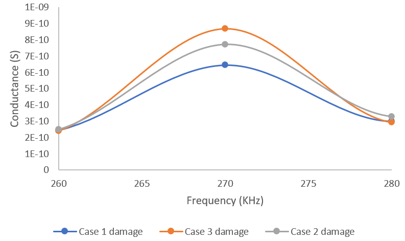
Fig.17 Conductance response obtained for frequency range of 260-280KHz
To get the quantitative measure of damage the root mean square deviation was find out for Case 1 damage it was 27.604%, for Case 2 damage it was 28.57%, for Case 3 damage it was 30.76%.
Conclusion
In this paper the electro-mechanical impedance technique was used that is very crucial in examining the behaviour of damage structure. In this technique, a PZT piezoelectric material was embedded in the structure that will convert mechanical energy into electrical energy. The type of PZT sensor used was PZT-4 whose size was 10×10×0.3mm3. The frequency domain analysis was done to get the conductance response for frequency range of 30-300KHz. For that, admittance reading was taken whose real part will give the conductance of the damage structure. Then, conductance and frequency graph were made that represents the signature of the damage structure. Then, RMSD values was find out that represents the quantitative measure of damage and that was increasing as the amount of damage increases.
References
[1] Silva DD, Sobrinho JM, Souto CR, Gomes RM. Application of electromechanical impedance technique in the monitoring of sigma phase embrittlement in duplex stainless steel. Materials Science and Engineering: A. 2020 Jun 24;788:139457. [2] Ali L, Khan S, Iqbal N, Bashmal S, Hameed H, Bai Y. An experimental study of damage detection on typical joints of jackets platform based on electro-mechanical impedance technique. Materials. 2021 Nov 25;14(23):7168. [3] Cherrier O, Selva P, Pommier-Budinger V, Lachaud F, Morlier J. Damage localization map using electromechanical impedance spectrums and inverse distance weighting interpolation: Experimental validation on thin composite structures. Structural Health Monitoring. 2013 Jul;12(4):311-24. [4] Sivasuriyan A, Vijayan DS, Górski W, Wodzy?ski ?, Vaverková MD, Koda E. Practical implementation of structural health monitoring in multi-story buildings. Buildings. 2021 Jun 20;11(6):263. [5] Baptista FG, Budoya DE, De Almeida VA, Ulson JA. An experimental study on the effect of temperature on piezoelectric sensors for impedance-based structural health monitoring. Sensors. 2014 Jan 10;14(1):1208-27. [6] Tang ZS, Lim YY, Smith ST, Padilla RV. Modelling of the electromechanical impedance technique for prediction of elastic modulus of structural adhesives. Structural Health Monitoring. 2021 Sep;20(5):2245-60. [7] Maurya KK, Rawat A, Jha G. Smart materials and electro-mechanical impedance technique: A review. Materials Today: Proceedings. 2020 Jan 1;33:4993-5000. [8] KOLLEPARA VM. FINITE ELEMENT MODELLING OF SMART STRUCTURES (Doctoral dissertation, INDIAN INSTITUTE OF TECHNOLOGY DELHI). [9] Gayakwad H, Thiyagarajan JS. Structural damage detection through EMI and wave propagation techniques using embedded PZT smart sensing units. Sensors. 2022 Mar 16;22(6):2296. [10] Sivakumar N, Kanagasabapathy H, Srikanth HP. Static multiple, distributed piezoelectric actuator structural deformation and bending analysis using comsol. Materials today: proceedings. 2018 Jan 1;5(5):11516-25. [11] BDV CM. Numerical simulation for health monitoring of thin simply supported plate using PZT transducers. Materials Today: Proceedings. 2021 Jan 1;45:3492-8. [12] Moharana S, Bhalla S. Numerical investigations of shear lag effect on PZT-structure interaction: review and application. Current Science. 2012 Sep 25:685-96. [13] Campeiro LM, da Silveira RZ, Baptista FG. Impedance-based damage detection under noise and vibration effects. Structural Health Monitoring. 2018 May;17(3):654-67. [14] Giurgiutiu V, Rogers CA. Recent advancements in the electromechanical (E/M) impedance method for structural health monitoring and NDE. In Smart structures and materials 1998: Smart structures and integrated systems 1998 Jul 27 (Vol. 3329, pp. 536-547). SPIE [15] Lim YY, Soh CK. Towards more accurate numerical modelling of impedance based high frequency harmonic vibration. Smart Materials and Structures. 2014 Feb 14;23(3):035017.
Copyright
Copyright © 2024 Laxmi Bhalla, Abhishek Mishra, Sachin Kumar Singh. This is an open access article distributed under the Creative Commons Attribution License, which permits unrestricted use, distribution, and reproduction in any medium, provided the original work is properly cited.

Download Paper
Paper Id : IJRASET64843
Publish Date : 2024-10-27
ISSN : 2321-9653
Publisher Name : IJRASET
DOI Link : Click Here
 Submit Paper Online

