Ijraset Journal For Research in Applied Science and Engineering Technology
- Home / Ijraset
- On This Page
- Abstract
- Introduction
- Conclusion
- References
- Copyright
Optimization and Analysis of 4-Wheeler Connecting Rod for Weight Reduction and Performance Enhancement
Authors: Mr. Manohar Gangarkar, Prof. Prashant Karajagi
DOI Link: https://doi.org/10.22214/ijraset.2024.61708
Certificate: View Certificate
Abstract
Composite materials are now a day widely used in the engineering field. The general characteristics possessed by the composite materials are found to be the reason for using it in the automotive applications. The connecting rod is a major link inside of combustion engine. It connects the piston to the crankshaft and is responsible for transferring power from the piston to the crankshaft. It must work on high RPM because of which it has to bear severe stresses which make its design vital for internal combustion engine. In this project, design, & analysis of the 4wheeler connecting rod is done. The CATIA V5 R21 software has been used for designing the connecting rod 3D model and then the designed connecting rod model is imported into the ANSYS software in which the design is meshed and analyzed by using the Finite Element Method (FEM) and the result is manipulated. Static analysis of existing and composite connecting rod will be performed. Results of the analysis are also validated by using UTM testin
Introduction
I. INTRODUCTION
The connecting rod is a major link inside a combustion engine. It connects the piston to the crankshaft and is responsible for transferring power from the piston to the crankshaft and sending it to the transmission. The objective of C.R. is to transmit push & pull from the piston pin to the crank pin and then converts reciprocating motion of the piston into the rotary motion of crank. The components are big shank, a small end, and a big end. The cross section of shank may be rectangular, circular, tubular, I- Section, + -section or ellipsoidal-Section. It sustains force generated by mass & fuel combustion. The resulting bending stresses appear due to eccentricities, crank shaft, case wall deformation & rotational mass.
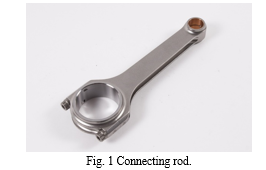
There are different types of materials and production methods used in the creation of connecting rods. The most common types of Connecting rods are steel and aluminium. The most common types of manufacturing processes are casting, forging and powdered metallurgy. Connecting rods are widely used in variety of engines such as, in-line engines, V-engine, opposed cylinder engines, radial engines, and opposed-piston engines. A connecting rod consists of a pin-end, a shank section, and a crank-end. Pin-end and crank-end pinholes at the upper and lower ends are machined to permit accurate fitting of bearings. The function of connecting rod is to transmit the thrust of the piston to the crankshaft. Figure shows the role of connecting rod in the conversion of reciprocating motion into rotary motion. A four-stroke engine is the most common type. The four strokes are intake, compression, power, and exhaust. Each stroke requires approximately 180 degrees of crankshaft rotation, so the complete cycle would take 720 degrees. Each stroke plays a very important role in the combustion process.
In the intake cycle, while the piston moves downward, one of the valves open. This creates a vacuum, and an air-fuel mixture is sucked into the chamber (Figure 1). During the second stroke compression occurs. In compression both valves are closed, and the piston moves upward and thus creates a pressure on the piston, see Figure 2. The next stroke is power. During this process the compressed air-fuel mixture is ignited with a spark, causing a tremendous pressure as the fuel burns. The forces exerted by piston transmitted through the connecting rod moves the crankshaft, see Figure 3. Finally, the exhaust stroke occurs. In this stroke, the exhaust valve opens, as the piston moves back upwards, it forces all the air out of the chamber and thus which completes the cycle of crankshaft rotation Figure 4.
Connecting rods are highly dynamically loaded components used for power transmission in combustion engines. The optimization of connecting rod had already started as early year 1983 by Webster and his team. However, each day consumers are looking for the best from the best. That’s why the optimization is important especially in automotive industry. Optimization of the component is to make the less time to produce the product that is stronger, lighter and less cost. The design and weight of the connecting rod influence on car performance. Hence, it is effect on the car manufacture credibility. Change in the structural design and material will be significant increments in weight and performance of the engine.
FEA approach deals with structural analysis along with various parameters which affects its working & define best solution to overcome the barriers associated with it. The structural analysis allows stresses & strains to be calculated in FEA, by using the structural model. The structural analysis performed to create high & low stresses region from the input of the material, loads, boundary condition. FEA approach was adopted in structural analysis to overcome the barriers associated with the geometry & boundary condition. It is used to improve optimize design.
A connecting rod is also called a Con Rod and is the connecting point between the crankshaft and the piston within an engine. The role of the connecting rod and the crank is to convert the piston's reciprocating motion to the crankshaft's rotational motion. The linking rod transmits from the piston the compressive and tensile forces and rotates at both ends. Connecting rods are commonly used in internal combustion engines or in steam engines. In the beginning of 1700’s, the first steam engine used a chain drive instead of a connecting rod because the piston only generated force in one direction. Double acting steam engines, so that the force was generated in both directions, led to the invention of connecting rods to turn one type of motion into another (rotational). The basic steam engine design is a cross head with the joint between the connecting rod and the piston mounted outside the cylinder, requiring a seal around the piston rod. The cranks in a steam locomotive are usually mounted directly on the driving wheels. The connecting rod is being worked out between the crosshead and crank pin. The connecting rods are called lateral rods, or coupling rods, in diesel locomotives. The design of the internal combustion engines connecting rod consists of the small end, the rod and the wide end. The small end is attached to the gudgeon pin, as the wrist pin or piston pin will swivel within the piston. The broad end is connected to the crank pin with the aid of a single bearing to prevent friction, whereas a rolling-element bearing is used in small engines to avoid the need for a pumped lubrication unit. The pinhole is drilled through the bearing of a small circular hole's wide end so that the oil used for lubrication leaks to the wall's thrust side to allow the piston and piston rings to move. A continuous programming process involving a series of programs that will produce a given number of outputs that satisfy the specific constraints is known as generative design. Generative design is becoming increasingly important. Except for those designers with very primitive programming skills, the modern programming environment has made it very simple. This approach offers a solution to very difficult problems that are typically very resource-intensive, making it a very appealing choice. This is also encouraged by instruments in commercially available CAD kits. To optimize part design automatically, generative design is a novel approach. The design must achieve the optimal solution, in relation to design parameters, requirements and limits. A connecting rod for single cylinder 4-stroke petrol engine was designed and analysis and topology optimization of the same connecting rod was carried out. Attributes like material and shape of the connecting rod and manufacturing process of the connecting rod was selected [6]. All these papers discussed about the designing of connecting rod, analysis of connecting rod, choosing attributes and manufacturing process and about the importance of generative design. Generative design is an important skill which should be acquired by all the designers to produce highly efficient optimized products. It can be particularly useful to produce lightweight highly complex products. The main objective was to explore the cost and weight reduction possibilities, and this was possible by labouring generative design during the designing of the connecting rod. A connecting rod was designed, and generative design was opted for weight reduction. A proper alternative material suitable for addictive manufacturing of the connecting rod was proposed.
A connecting rod is the link between the reciprocating piston and rotating crank shaft. Small end of the connecting rod is connected to the piston by means of gudgeon pin. The big end of the connecting rod is connected to the crankshaft. A combination of axial and bending stresses act on the rod in operation. The axial stresses are product due to cylinder gas pressure and the inertia force arising on account of reciprocating motion.
Whereas bending stresses are caused due to the centrifugal effects. To provide the maximum rigidity with minimum weight, the cross section of the connecting rod is made as I – section and end of the rod is a solid eye or a split eye, this end holding the piston pin. The big end works on the crank pin and is always split. In some connecting rods, a hole is drilled between two ends for carrying lubricating oil from the big end to the small end for lubrication of piston and the piston pin axial stresses. Therefore in order to study the strain intensity, stress concentration and deformation in the crank end of the connection rod, firstly based on the working parameter and the vehicle chosen the design parameter or dimensions of the connecting rod is calculated and results thus achieved will provide us the required outcome of the work done here .Also further study can also be carried out later on for the dynamic loading working conditions of the connecting rod and also improvement in design can also be made for operation condition and longer life cycle against failure.
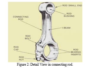
Every Internal Combustion (I.C.) engine consists of mainly cylinder, piston, connecting rod, crank and crank shaft. The Connecting Rod is one of the important parts of an engine. Its work is to transmit the thrust of piston from piston pin generated by the burnt gass pressure to the other part of engine called Crank via crank pin. It has two ends one is called small or piston end and other one is big or crank end. The big end makes a joint with crank or crank shaft by crank pin and small end make a joint with piston-by-piston pin. It gives the rotating motion to the crank shaft by converting the reciprocating motion of piston into rotating motion. The connecting rod should be such that which can be withstand the maximum load without any failure during high cycle fatigue in operation. The fracture toughness also should be such that it does not go below a certain minimum limit. A further need is that the connecting rod should not buckle during operation. These requirements are used to select an appropriate cross section and material for manufacture. The connecting rod generally has a long shank, a small end, and a big end. According to the requirements, the cross-section of the shank may be rectangular, circular, tubular, I-section, or H-section. It has been observing that circular section is used for low-speed engines and I-section is used for high-speed engines. In a long research span it has been noted that during reciprocating motion of the piston a wear of cylinder wall occurs, which is caused by sideways force of piston acting on cylinder wall and results in an oval cross-section rather than being circular.
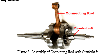
The connecting rod is a vital component in internal combustion engines, responsible for converting the reciprocating motion of the piston into the rotary motion of the crankshaft. It consists of a small end connected to the piston pin and a big end connected to the crankpin. Among the various cross-sectional shapes available, the I-section is commonly preferred due to its superior characteristics. To enhance the strength and stiffness of connecting rods, adjustments can be made to their cross-sectional shape or specific parameters. Additionally, material selection plays a crucial role in reducing weight and cost. However, ensuring the structural integrity of the connecting rod requires thorough stress analysis using advanced tools such as ANSYS. Connecting rods are manufactured through different processes. While hot forging is a widely used method, it leads to substantial material wastage (approximately 20 to 40%) due to flash formation. To address this, fleshless forging in a closed cavity is employed to minimize material waste. In heavy vehicles, where optimal performance is essential, achieving superior mechanical properties of connecting rods is a priority. Traditional quenching in oil may not meet the desired requirements, but quenching in aqueous polymer water shows potential for improving mechanical properties. This involves compacting metal powders and subjecting them to controlled sintering conditions. In conclusion, connecting rods play a critical role in the efficient operation of internal combustion engines. Optimizing their design, material selection, and manufacturing processes is key to achieving enhanced performance, durability, and cost-effectiveness. Thorough stress analysis and consideration of suitable manufacturing methods contribute to the production of reliable and high-performance connecting rods.
Connecting rods can be classified based on various factors, including their design, application, and material composition. The following are common classifications of connecting rods:
- Design-based Classification
a. I-Section Connecting Rod: This design features a central beam with symmetrical flanges on either side, resembling the shape of the letter "I." It offers a good balance of strength and weight and is commonly used in many internal combustion engines.
b. H-Section Connecting Rod: With an H-shaped cross-section, this design includes a thicker central beam and two flanges on each side. H-section connecting rods provide increased strength and stiffness, making them suitable for high-performance engines.
2. Application-based Classification
a. Automotive Connecting Rod: Designed specifically for use in internal combustion engines of automobiles, trucks, and motorcycles. They are engineered to withstand high levels of stress and provide reliable performance.
b. Marine Connecting Rod: These connecting rods are specifically designed for marine engines used in boats, ships, and another watercraft. They are built to withstand the unique challenges of marine environments, including corrosion and high loads.
3. Material-based Classification
a. Steel Connecting Rod: Made from various steel alloys, these connecting rods offer excellent strength, durability, and resistance to high temperatures. They are commonly used in a wide range of engines.
b. Aluminium Connecting Rod: Constructed from aluminium alloys, these connecting rods are lightweight, which helps reduce the reciprocating mass in the engine. They are often used in performance-oriented engines where weight reduction is crucial.
c. Titanium Connecting Rod: Manufactured from titanium alloys, these connecting rods combine high strength with a lightweight construction. They are commonly found in high-performance engines where weight reduction is critical, such as racing engines.
d. Composite Connecting Rod: These connecting rods are made using composite materials, typically carbon fiber reinforced polymers. They offer an excellent strength-to-weight ratio and are used in high-performance and racing applications.
4. Engine configuration-based classification: a. Inline Connecting Rod: Found in engines with a straight or inline cylinder arrangement. Each connecting rod connects to a separate crankpin on the crankshaft. b. V-Engine Connecting Rod: Used in V-shaped engines, where the cylinders are arranged in a V-configuration. The connecting rods are designed to connect the pistons to the crankshaft at the respective crankpins. c. Boxer Engine Connecting Rod: Found in horizontally opposed or "boxer" engines, where the cylinders are arranged in a horizontally opposed configuration. The connecting rods are designed to work with the unique layout of these engines.
5. These classifications help categorize connecting rods based on their design, intended application, material composition, and compatibility with specific engine configurations.
II. LITERETAURE REVIEW
- Nishanth R, Sreedharan M et.al “Generative Design Optimization and Analysis of Connecting Rod for Weight Reduction and Performance Enhancement” This research paper aims to explore opportunities for weight and cost reduction in the design and development of connecting rods. Two phases are involved in the analysis. The first part is to analyze the loads (compressive and tensile loads) acting on the connecting rod as a function of time to optimize its weight and manufacturing cost using generative design. The generative design is an iterative design process that produces a certain number of outputs based on the power, stress and other constraints applied.
- D.Gopinatha ,Ch.V.Sushma” Design and Optimization of Four Wheeler Connecting Rod Using Finite Element Analysis” Every vehicle that uses an internal combustion engine requires at least one connecting rod depending upon the number of cylinders in the engine. It undergoes high cyclic loads of the order of 108 to109 cycles, which range from high compressive loads due to combustion, to high tensile loads due to inertia. Therefore, durability of the component is of critical importance. Due to these factors the connecting rod has been the topic of research for different aspects such as production, materials, performance simulation, etc.
- Pravardhan S. Shenoy et.al “Connecting Rod Optimization for Weight and Cost Reduction” An optimization study was performed on a steel forged connecting rod with a consideration for improvement in weight and production cost. Since the weight of the connecting rod has little influence on its total production cost, the cost and the weight were dealt with separately.
- S. Om Prakash, M. Natrayan et.al “Optimization of Connecting Rod for Weight Reduction by Finite Element Analysis” The main objective of this work is to explore weight and cost reduction opportunities in the design and production of a connecting rod, achieved by performing a detailed load analysis. The study deals with load and stress analysis of the connecting rod is done and then optimization is achieved by reducing the weight and cost. First part of the study analysis includes the determination of loads acting on the connecting rod as a function of time. This is done for finding out the minimum stress area and to remove the material in those areas.
- M Helal, B F Felemban , A Alharthi et.al “Dimensional structural mass optimization of forged steel connecting rod for aircraft piston engine” The connecting rod is an important component of the engine. It conveys the kinetic energy from the piston to the crankshaft. All cars and aircraft engines contain at least one connecting rod, which differs from one motor to another in terms of length, size, and shape. Hence, it is subjected to massive alternating load.
- Sourabh Mishra, Ruchika Saini et.al “Connecting Rod Deformation and Statical Stress Analysis Using Various Materials: A Review” In the world of engineering, connecting rods play a crucial role in ensuring that an engine runs smoothly and efficiently. Made from a variety of materials, these rods connect the pistons to the crankshaft, allowing for proper transfer of energy throughout the system. But with so many options available, which material is best? In this review paper, we will explore the advantages and disadvantages of various materials used for making connecting rods. From traditional steel advanced composites analysed using ANSYS FEA software, read on to discover how each material stacks up in terms of performance and durability. Based on previous research the objective of this review paper is “Deformation and Static Stress Analysis of Connecting Rod Using Various Materials
- Nkrumah Jacob Kwaku, Baba Ziblim et.al “Modal and Thermal Analysis of a Modified Connecting Rod of an Internal Combustion Engine Using Finite Element Method” The connecting rod is one of the most important moving components in an internal combustion engine. The present work determined the possibility of using aluminium alloy 7075 material to design and manufacture a connecting rod for weight optimisation without losing the strength of the connecting rod. It considered modal and thermal analyses to investigate the suitability of the material for connecting rod design.
- Durgesh Aawnre et.al “A-Review Paper and Parameter Discussion on Connecting Rod” This review paper focuses on providing a detailed analysis of connecting rods, which are crucial components in internal combustion engines. The paper explores the design, materials, manufacturing processes, and Key parameters that influence the performance and reliability of connecting rods. It also discusses recent Advancements in connecting rod technology and highlights future trends in this field. This review paper Provides an in-depth examination of connecting rods in internal combustion engines, encompassing their Design, materials, manufacturing processes, and critical parameters.
- K. Archana, Y. Anantha Reddy et.al “Topology Optimization of Connecting ROD using ANSYS Workbench 18.1” Topology Optimization (TO) advantages are comprehended to a more extent cause to manufacturing freedom that Additive Manufacturing (AM) offer, analyzed to other conventional manufacturing methods. AM has the advantage of designing shallow and critical patterns formerly not feasible, and consequently opens a whole new design spectrum. This paper study the capabilities of using topology optimization as a tool to find lighter and stronger patterns for the connecting rod in the engine.
- Dr.S. Selvakumar, Abhinand Pet.al “Analysis and Evaluation of connecting rod using composite materials (Al+SiC)” Connecting rod is one of the most important parts of the engine assembly as it acts as a arbitrator between piston set and crankshaft. It is transforming the reciprocating action of the piston to rotary action of the crank set. Also, it faces a lot of tensile and compressive loads during its lifetime. In general, these connecting rods are manufactured from carbon steel and in recent days aluminium alloys are also utilized or the services and its applications.
III. PROBLEM IDENTIFICATION
Each day consumers are looking for the best from the best. That’s why the material optimization is important in industry. Material Optimization of the component is to make the less time to produce the product that is stronger, lighter and less cost. The design and weight of the connecting rod influence on performance. Hence, it is effect on the manufacture credibility. The tensile and compressive stresses are produced due to pressure, and bending stresses are produced due to centrifugal effect & eccentricity. So, the connecting rods are designed generally of I-section to provide maximum rigidity with minimum weight. Change in the structural design and material will be significant increments in weight and performance.
A. Objectives
- The main aim of the project is to determine the Total deformation, Equivalent Stress of existing and composite connecting rod.
- In this Project, the static and modal FEA of the connecting rod has been performed using the ANSYS software.
- Optimize connecting rod are validated by using UTM testing.
- Comparative analysis between FEA & Experimental results.
B. Scope
- To study the existing connecting rod for possible designing.
- Learning and use of CATIA and ANSYS software.
- Loads and boundary conditions shall be applied to the model in the pre-processor. The input deck for the designated solver shall be prepared.
- Suitable solver for structural analysis (like ANSYS) would be deployed for finding the solution.
- Recommendation to be made upon evaluating the results.
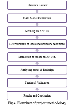
IV. METHODOLOGY
A. Literature Survey
Using the knowledge from literature review, we can know how the CAD model is to be prepared. The conditions required for applying various constraints and how the loads are applied is briefed about in the technical papers referred.
B. CAD Model Generation
- Getting input data on dimensions of connecting rod.
- Creating 3D model in CATIA.
C. Determination of Loads
Determination of different loads and boundary condition acting on the component by studying various ref papers, and different resources available.
D. Testing and Analysis
- Meshing the CAD model and applying the boundary conditions.
- Solve for the solution of meshed model using ANSYS.
E. Re-Design, Analysis and Results
- Making changes in CAD model for optimization.
- Carrying different iteration by removing material or changing topology based on ANSYS results.
- Check the maximum stress ensuring it is well within the safe region.
F. Fabrication, Experimental validation, and Result
- Fabrication of prototype.
- Suitable experimentation and comparison with present connecting rod.
- Validation of result by comparing with software results.
V. DESIGN
A. Computer Aided Design
Computers are sophisticated tools that are used in every facet of society to provide accuracy, flexibility, cost-saving, efficiency, record keeping, and vast storage, decision making tools and modeling. The use of computers to design two- or three-dimensional models of physical objects is known as computer aided design. Computer aided design is use of computer to aid in the design and especially the drafting of a part or product. It is both a visual and symbol-based method of communications whose conventions are particular to a specific technical field. Designers in architecture, electronics, aerospace and automotive engineering, for example, use Computer aided design systems and software's to prepare drawings and specifications that once could only be drawn or written by hand. Before CAD, manufactures and designers would have to build prototypes of automobiles, buildings, computer chips, and other products before the prototypes could be tested. CAD technology, however, allows users to rapidly produce a computer-generated prototype and then test and analyze the prototype under a variety of simulated conditions. Current CAD software packages range from 2D vector base drafting system to 3D solid and surface modelers. Modem CAD packages can also frequently allow rotations in three dimensions, allowing viewing of a designed object from any designed angle, even from the inside looking out. Manufacturers and designers also use CAD technology to study optimization, performance, and reliability problems in prototypes and in already exiting designs. Drawing can be modified and enhanced under the desired results are achieved. CAD is very useful for prototyping because it all allows designers to see problems before times and money is invested in an actual product.
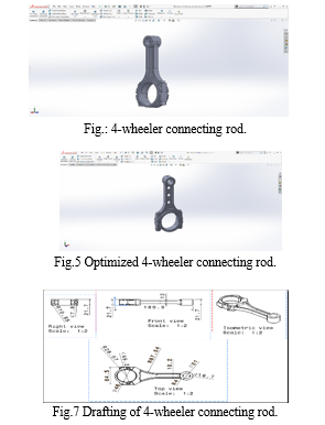
B. CAD Model
Computer-aided design (CAD) is the use of computer systems (or workstations) to aid in the creation, modification, analysis, or optimization of a design. CAD software is used to increase the productivity of the designer, improve the quality of design, improve communications through documentation, and to create a database for manufacturing. CAD output is often in the form of electronic files for print, machining, or other manufacturing operations. The term CADD (for Computer Aided Design and Drafting) is also used.
Its use in designing electronic systems is known as electronic design automation (EDA). In mechanical design it is known as mechanical design automation (MDA) or computer-aided drafting (CAD), which includes the process of creating a technical drawing with the use of computer software.
C. Calculations
TATA INDICA ENGINE Specifications
Bore diameter – 75 mm.
Stroke length – 95 mm
Bore x Stroke (mm) = 75 × 95
Displacement – 3.14/2 x (Bore diameter)2 x Stroke length.
Displacement = 419.4 CC
Maximum Power = 60 PS @ 4500 rpm
Maximum Torque = 105 Nm @ 2500 rpm
Compression Ratio = 9/1
Density of Petrol C8H18 = 737.22 kg/m3 = 737.22E-9 kg/mm3
Temperature = 600 F= 288.8550 K
Molecular Weight of Petrol - 114.228 g/mole
From Gas Equation,
PV = mRspecific T
P = Pressure, V= Volume, m = Mass, T = Ideal room temperature and Rspecific = Specific gas constant
Mass = Density × Volume
= 737.22E-9 x 419.4 X E3
= 0.309 kg
R specific = R / M
= 8.314 / 0.309 = 26.88 J / kgK
Maximum pressure exerted on the surface of small piston end.
P = (0.30 × 26.88 × 288.85) /4.19 X ????-4
P = 5.5 MPa.
MAXIMUM PRESSURE EXERTED ON SMALL END OF PISTON IS CONSIDERED AROUND 6MPa.
VI. FINITE ELEMENT ANALYSIS
A. Introduction of Finite Element Analysis
The finite element analysis (FEA) is a problem-solving approach for the practical (engineering) problems. The problems are first converted to matrix and partial differential equation forms. Eventually the partial differential and integral equations are being solved to reach the solution of the problem. The volume of the equations to be solved is usually so large that arriving solution without using computer is practically impossible. And, that’s why the need of different FEA packages is felt. There are many FEA packages available for different applications. Some popular FEA packages are Pro Mechanica, ANSYS, NASTRAN, and Gambit etc.
In mathematics, the finite element analysis (FEA) is a numerical technique for finding approximate solutions to boundary value problems for partial differential equations. It uses subdivision of a whole problem domain into simpler parts, called finite elements, and variational methods from the calculus of variations to solve the problem by minimizing an associated error function. Analogous to the idea that connecting many tiny straight lines can approximate a larger circle, FEA encompasses methods for connecting many simple element equations over many small sub domains, named finite elements, to approximate a more complex equation over a larger domain.
Finite element analysis (FEA) is a useful and powerful technique for determining stresses and strains in structures or components too complex to analyze by strictly analytical methods. With this technique, the structure or component is broken down into many small pieces (finite number of elements) of various types, sizes, and shapes. The elements are assumed to have a simplified pattern of deformation (linear or quadratic etc.) and are connected at “nodes” normally located at corners or edges of the elements. The elements are then assembled mathematically using basic rules of structural mechanics, i.e., equilibrium of forces and continuity of displacements, resulting in a large system of simultaneous equations. By solving these large simultaneous equations system with the help of a computer, the deformed shape of the structure or component under load may be obtained. Based on that, stresses and strains may be calculated. The finite element analysis (FEA) is probably the most versatile way of calculating stress intensity factors. This method primarily involves the evaluation of displacements at nodal points of the body which has been idealized into a system of elements connected at the nodal points. The FEA has become a powerful tool for the numerical solution of a wide range of engineering problems. The FEA has been extensively used to solve problems involving irregular regions and complicated modals.
B. Steps of Finite Element Analysis
FEA solution of engineering problems, such as finding deflections and stresses in a structure, requires three steps:
- Pre-processing
- Solution
- Post processing
A brief description of each of these steps follows.
- Step1: Pre-processing
Using a CAD program that either comes with the FEA software or 3D CAD modeling tools like Pro-E, Catia, and solid Edge etc. provided by another software vendor, the structure is modeled. The final FEA model consists of several elements that collectively represent the entire structure. The elements not only represent segments of the structure, they also simulate its mechanical behaviour and properties.
Regions where geometry is complex (curves, notches, holes, etc.) require increased number of elements to accurately represent the shape, whereas, the regions with simple geometry can be represented by coarser mesh (or fewer elements). The selection of proper elements requires prior experience with FEA, knowledge of structure’s behaviour, available elements in the software and their characteristics, etc.
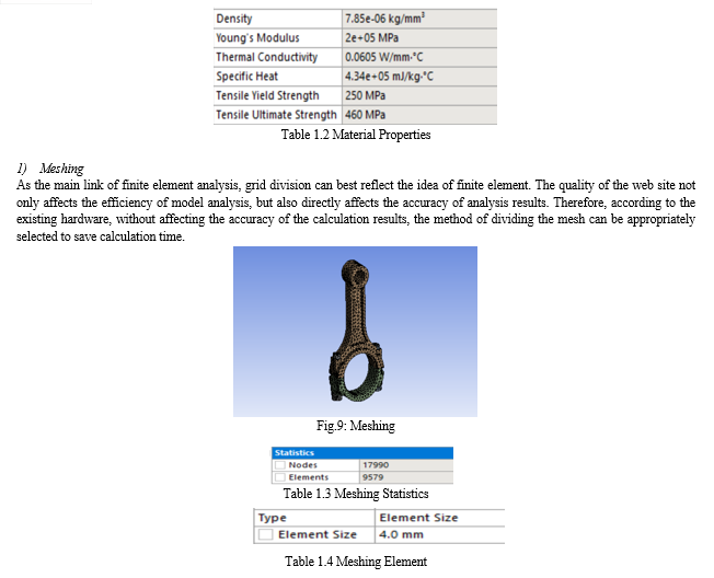
The elements are joined at the nodes, or common points. In the pre-processor phase, along with the geometry of the structure, the constraints, loads and mechanical properties of the structure are defined. Thus, in pre-processing, the entire structure is completely defined by the geometric model. The structure represented by nodes and elements is called “mesh”.
2. Step 2: Solution
In this step, the geometry, constraints, mechanical properties and loads are applied to generate matrix equations for each element, which are then assembled to generate a global matrix equation of the structure. The form of the individual equations, as well as the structural equation is always,
{F} = [K] {u}
Where
{F} = External force matrix,
[K] = Global stiffness matrix,
{u} = Displacement matrix.
The equation is then solved for deflections. Using the deflection values, strain, stress, and reactions are calculated. All the results are stored and can be used to create graphic plots and charts in the post analysis.
3. Step 3: Post processing
This is the last step in a finite element analysis. Results obtained in step 2 are usually in the form of raw data and difficult to interpret. In post analysis, a CAD program is utilized to manipulate the data for generating deflected shape of the structure, creating stress plots, animation, etc. A graphical representation of the results is very useful in understanding behaviour of the structure.
In present research for analysis ANSYS (Analysis System) software is used. Basically, its present FEM method to solve any problem. Following are steps in detail.
- Geometry
- Discretization (Meshing)
- Boundary condition
- Solve (Solution)
- Interpretation of results
C. Geometry
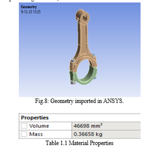
ANSYS Workbench 21.0 platform to perform modal analysis of thrust coupling. ANSYS Workbench 21.0, as the most advanced CAE software, provides users with simulation modules including: structure, fluid, electromagnetic, heat transfer, and other fields. It is the industry's most advanced engineering simulation technology integration platform, with intuitive and friendly interface, convenient pre-processing and post-processing functions, and its extensive solution functions.
2) Element Types
When geometries are complex or the range of length scales of the flow is large, a triangular/tetrahedral mesh can be created with far fewer cells than the equivalent mesh consisting of quadrilateral/hexahedral elements. This is because a triangular/tetrahedral mesh allows clustering of cells in selected regions of the flow domain. Structured quadrilateral/hexahedral meshes will generally force cells to be placed in regions where they are not needed. Unstructured quadrilateral/hexahedral meshes offer many of the advantages of triangular/tetrahedral meshes for moderately complex geometries.
- For simple geometries, use quadrilateral/hexahedral meshes.
- For moderately complex geometries, use unstructured quadrilateral/hexahedral meshes.
- For relatively complex geometries, use triangular/tetrahedral meshes with prism layers.
- For extremely complex geometries, use pure triangular/tetrahedral meshes.
3) Boundary Condition
After the material and 4-wheeler connecting rod geometry have been set, the boundary conditions of 4 wheeler connecting rod need to be applied in ANSYS Mechanical to simulate its operating conditions. Under Static Structural analysis, 6 MPa of pressure is applied on top surface of 4-wheeler connecting rod. to determine stress and deformation and compare with carbon reinforced connecting rod.
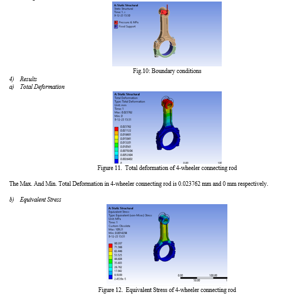
The Max. and Min. Stress Distribution in 4-wheeler connecting rod is 80.287 MPa and 2.4539e-5 MPa respectively.
D. Topology Optimization
Topology optimization is a mathematical approach that optimizes material layout within a given design space, for a given set of loads and boundary conditions such that the resulting layout meets a prescribed set of performance targets.
- Basic Theory
There are three kinds of structure optimization,
- Size Optimization
- Shape Optimization
- Topology Optimization
Three optimization methods correspond to the three stages of the product design process, namely the detailed design, basic design and conceptual design. Size optimization keeps the structural shape and topology structure invariant, to optimize the various parameters of structure, such as thickness, section size of beam, materials’ properties; shape optimization maintains the topology structure, to change the boundary of structure and shape, seek the most suitable structure boundary situation and shape; topology optimization is to find the optimal path of materials’ distribution in a continuous domain which meet the displacement and stress conditions in structure, make a certain performance optimal. Thus, compared to size and shape optimization, topology optimization with more freedom degree and greater design space, its greatest feature is under uncertain structural shape, according to the known boundary condition and a given load to determine the reasonable structure, both for the conceptual design of new products and improvement design for existing products, it is the most promising aspect of structural optimization. For continuous structure topology optimization, there are some mature methods like: uniform method, evolutionary structural optimization method, variable density method etc. Uniform method introduced cell structure of microstructure (unit cell) in the elements of the structure, each unit cell has three forms, namely non-material voids (size = 1), isotropic-material entity medium (size = 0) and orthotropic-material opening-hole medium (0 < size < 1). Wherein the distribution of each form will be able to describe the form of topology and the shape of structure; evolutionary structural optimization method believes that stress in any parts of the structure should under the same level in an ideal structure. That means the local material with a low stress state is not fully utilized, so you can delete the material artificially. So gradually remove material which in a low stress state, and then delete the update rate, so optimized structure becomes more uniform. Variable density method is used to conduct optimization in this paper. The basic idea is to introduce a hypothetical material which density is variable and range from 0 to 1.
After changing the continuous structure to finite element model, then making per units’ density as the design variables, to convert topology optimization problem into the optimal distribution of material, while in order to suppress the intermediate density of the material (material between void and entities), the introduction of a interpolation penalty factor used to describe the relationship between Young’s modulus and density of the material which shown as the following formula:
E = xp E0
where: p—interpolation penalty factor (p > 1); E0—Young’s modulus of densified material unit; E—Young’s modulus after interpolation. So that the original model with intermediate density will be eliminated or replaced by densified material and will achieve optimal results which close to the entity. Therefore, during topology optimization, variable is relative density of units, then structural topology optimization problem is converted into the optimal distribution of the material.
2. Process of Topology Optimization
Based on Hyper Works platform topology optimization holder, first, according to the engine mounting position, we establish the three-dimensional geometric model of engine bracket, and then pre-treated in HyperMesh, define design area, objective function and constraints under the optimization panel, finally operate topology optimization which design process is as Figure 2.
3. Analysis
To establish the geometry model by CATIA, then input the geometry to the ANSY to carry out pre-treatment operations like geometry clean up, meshing, loads, constraints, etc.
Initially we need to collect the information regarding different loads acting on the bracket and the packaging data for fixing design space. The base bracket results from testing and finite element analysis (FEA) point of view for evaluating final optimized design.
4. Steps in Topology Optimization
The topology optimization consists of the following sequence of steps.
• Define the design space
• Define optimization parameters
• Material removal process and detail design
5. Defining the Optimization Parameters
The aim of topology optimization in this project is to minimize the volume without affecting the bracket stiffness and strength compared to base bracket, so the design objective is taken as to minimize the volume. Following parameters are defined as constrains:
1. Allowable stress limit value is defined as stress constraints from durability point of view
2. Single draw direction is defined as manufacturing constraint.
8. Material Removal Process and Detail Design
The optimization process took some iteration to remove the unnecessary material from the design space. The output of the topology optimization, an intermediate model which may be called a topology-based model, is constructed by removing unnecessary materials from the rough conceptual model.
7. Additive Manufacturing
Without manufacturing constraints, optimized components often have complex geometries. Recent developments in Additive Manufacturing (3D printing) enable the fabrication of these optimized designs without compromise. Topology optimization forms the natural design technology for Additive Manufacturing, as it fully exploits its potential.
8. Shape Optimization
Where topology optimization excels at automated concept generation, shape optimization allows for efficient final fine tuning of designs. However, every fabrication technique has its shape/property accuracy limitations, particularly at the micro scale. Our activities on shape optimization concentrate on dealing with fabrication inaccuracy and optimizing for robustness.
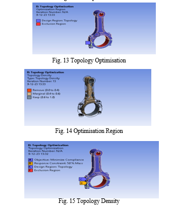
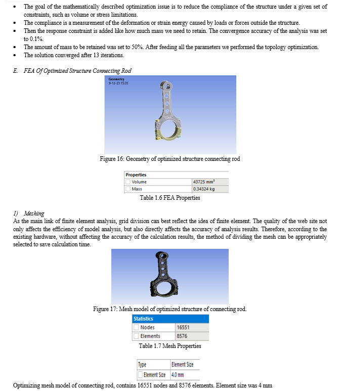
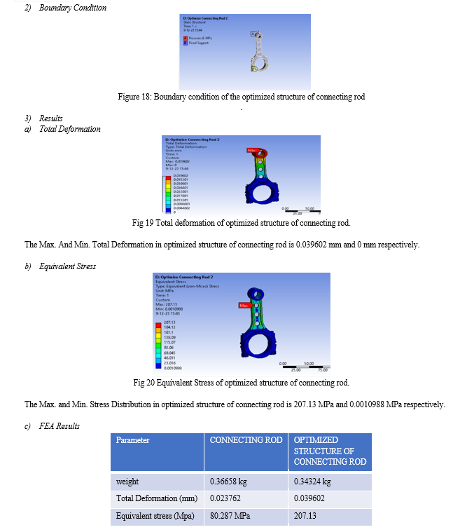
Using the above structural analysis and transferring the data to the structural optimization. After this step we need to add the optimization region for the piston. In our case, the piston connecting rod has the shell and the core part. So, the scope region for the topology optimization was for core and the exclusion region was kept for the shell.
Conclusion
1) The design and static structural analysis of 4-wheeler connecting rod has been carried out. 2) The stress and displacements have been calculated using ANSYS 21 for 4-wheeler connecting rod. From the static analysis results it is found that there is a maximum displacement of 0.023762 mm and maximum equivalent stress of 80.287 MPa. By analyzing the design, it was found that all the stresses in the 4-wheeler connecting rod were well less than the allowable limits and with good factor of safety. 3) Thus, a total weight reduction of 23.34 gms was achieved. Initial weight was 366.58 g whereas final weight was 343.24 g. 4) So, we have successfully reduced the weight of existing connecting rod by 6.36 % using optimized structure of connecting rod.
References
[1] Nishanth R, Sreedharan M et.al “Generative Design Optimization and Analysis of Connecting Rod for Weight Reduction and Performance Enhancement”- Journal of Physics: Conference Series 1969 (2021) 012022 [2] D.Gopinatha ,Ch.V.Sushma” Design and Optimization of Four Wheeler Connecting Rod Using Finite Element Analysis” -Materials Today: Proceedings 2 ( 2015 ) 2291 – 2299 [3] Pravardhan S. Shenoy et.al “Connecting Rod Optimization for Weight and Cost Reduction” -August 19, 2018 [4] S. Om Prakash, M. Natrayan et.al “Optimization of Connecting Rod for Weight Reduction by Finite Element Analysis” -30 November 2018 [5] M Helal, B F Felemban, A Alharthi et.al “Dimensional structural mass optimization of forged steel connecting rod for aircraft piston engine”- ASAT-19 2021 [6] Sourabh Mishra, Ruchika Saini et.al “Connecting Rod Deformation and Statical Stress Analysis Using Various Materials: A Review”- Volume 11 Issue VIII Aug 2023 [7] Nkrumah Jacob Kwaku, Baba Ziblim et.al “Modal and Thermal Analysis of a Modified Connecting Rod of an Internal Combustion Engine Using Finite Element Method”- Jul. 25, 2023 [8] Durgesh Aawnre et.al “A-Review Paper and Parameter Discussion on Connecting Rod”- Vol 4, no 6, pp 2472-2475 June 2023 [9] K. Archana, Y. Anantha Reddy et.al “TOPOLOGY OPTIMIZATION OF CONNECTING ROD USING ANSYS WORKBENCH 18.1”- Volume 8, Issue 5 May 2020 [10] Dr.S. Selvakumar, Abhinand Pet.al “Analysis and Evaluation of connecting rod using composite materials (Al+SiC)”- Volume 3, Issue 3 Mar. 2021, pp: 01-11
Copyright
Copyright © 2024 Mr. Manohar Gangarkar, Prof. Prashant Karajagi. This is an open access article distributed under the Creative Commons Attribution License, which permits unrestricted use, distribution, and reproduction in any medium, provided the original work is properly cited.

Download Paper
Paper Id : IJRASET61708
Publish Date : 2024-05-06
ISSN : 2321-9653
Publisher Name : IJRASET
DOI Link : Click Here
 Submit Paper Online

