Ijraset Journal For Research in Applied Science and Engineering Technology
- Home / Ijraset
- On This Page
- Abstract
- Introduction
- Conclusion
- References
- Copyright
A Parametric Analysis of Wind-Loaded High-Rise Constructions in Various Terrain Types with Bracing
Authors: Ashwini Arikar, Dr. Tushar G. Shende
DOI Link: https://doi.org/10.22214/ijraset.2024.62623
Certificate: View Certificate
Abstract
This study tries to provide a hypothetical structural design for a tall building in a city. It is very important for civil engineering students to think about how structural systems can enhance the architectural expression of a building. Wind is the governing load when building high-rise structures in the city. A building can be structurally improved to resist wind pressure by making changes to the basic design, which gives it a unique architectural expression. In this study, G+10 and G+20 storey structures is designed and compared in two terrain categories and subjected to wind load. The ruggedness of the environment where the fabric structure is located is measured by the Terrain category. Wind speed, wind direction, and exposure to the elements are examples of such variables. Earthquake and wind loads are applied to the ETABS model according to the given National Standards. Finally, it is determined how strong and flexible the structure is under these stresses. The output of the calculation program and additional calculated products are compared to the Indian limit for structural serviceability.
Introduction
I. INTRODUCTION
Lateral forces from wind, earthquakes, and imbalance can produce large torsional forces. Settlement loads, in addition to the weight of people and buildings. Shear failure consequently happens. Earthquakes and wind are examples of lateral stress that the bracing can withstand. Lateral pressures are frequently used to support high-rise structures. To maintain their integrity, structures that are susceptible to lateral loads from events like earthquakes and wind forces need to be reinforced. These structural systems, which are composed of reinforced concrete, unreinforced plywood or solid wood, and reinforced masonry, are separated into braced joints, braced frames, shear panels, and staggered walls. This article's goal is to give a summary of the substantial research done to enhance braces and how they behave under lateral loads. High-rise soft floor constructions are being used in India together with low-rise buildings because the supports can hold the majority of the lower part of the structure and the frame can carry the lateral loads on the top part of the structure. On the upper stories are residential structures, and it functions as a garage and parking area. The size and placement of the bracings could make a big difference. There is no universal agreement on how bracings respond at various opening sites, despite the fact that it is well accepted that openings have a considerable impact on the structural reaction of bracings. They might be able to create bracings at suitable structural locations with an effective lateral force resisting mechanism.
A. Types of Loads
- Dead Load
- Live Load
- Wind Load
- Snow Load
- Earthquake Load
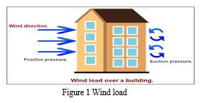
B. Indian Standard Codes used for Wind Load Study
The code used for wind load is IS 875-2015 (Part 3). The wind is the air that is moving relative to the earth's surface. The rotation of the planet and changes in terrestrial radiation are the fundamental causes of wind. Convection, whether uphill or downwards, is predominantly caused by radiation impacts. At high wind speeds, the wind usually travels horizontally to the ground. On average, the term "wind" only refers to horizontal winds because the vertical aspect of the atmosphere's movement is minimal. As a result, a vertical wind is always referred to as such. Anemometers, also known as anemometers, are used to measure wind speed and are mounted on weather stations between 10 and 30 meters above ground. Cyclonic storms, thunderstorms, dust storms, and intense monsoons are all accompanied by extremely strong winds (greater than 80 km/h).
C. Bracings
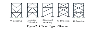
The bracing portion of a building's structure is required for its stability during an earthquake. The bracing configuration has the potential to significantly impact a steel-framed building's overall seismic performance. The ability to resist wind or seismic loads is driving the enlargement of many different elements of structure. One such structural system that is an intrinsic element of the frame is the bracing system. Before determining the optimal kind or efficient placement of bracing, such a structure must be evaluated. Braced Frame Systems structural system comprises of framed structures with particular bays braced across the building's elevation. Braces are supplied in both plan orientations to ensure that the structure does not twist due to unsymmetrical rigidity in plan.
Type of Bracings
- Single diagonals
- Cross bracings
- K-bracings
- V-bracings
II. PROBLEM STATEMENT
- Most of the research paper shows that wind load done on G+10, G+14, G+15 and G+ 20 separately, so it is need of comparative study. In this research G+10 and G+20 are to be considered.
- Most of the researcher to study on bending moment, base shear, joint displacement separately so it is need of comparison of all properties
- To reduce the effect of lateral load with bracing and compare their result data to analyse them to understanding of wind load design concept on the building.
- Learning of analysis and design methodology which can be very useful in the field.
III. OBJECTIVES
- To study the various types of terrain, wind load, earthquake load as per Indian Standard.
- To research and analysis of the impact of wind load on G+10 and G+20 building in various terrain.
- To compare the results of bending moments, shear force, storey displacement, stiffness and base shear.
- To study the changes in bending moments, shear force, storey displacement, stiffness and base shear due to provision of bracing.
IV. METHODOLOGY
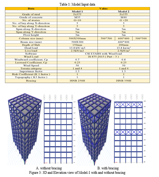
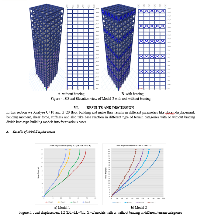
In this research work prepares G+10 and G+20 structures in with or without bracing in terrain category 1 & 4 of wind load as on IS code. Total 8 no. of cases for both models prepared to study. Terrain Category is a measure of the severity of the environment in which the Fabric Structure will be located. This can include factors such as wind speed, wind direction, and exposure to the elements.
The four main categories are:
- Terrain Category 1: Exposed, flat, treeless, no surrounding obstacles
- Terrain Category 2: Open terrain including grassland, with well-scattered obstructions at a frequency of no more than 2 obstructions per meter.
- Terrain Category 3: Terrain with numerous, closely-spaced obstructions
- Terrain Category 4: Terrain with numerous large high closely spaced obstructions.
V. MODEL GEOMETRY
In this portion we analyses models geometrical data and their 3D models.
Conclusion
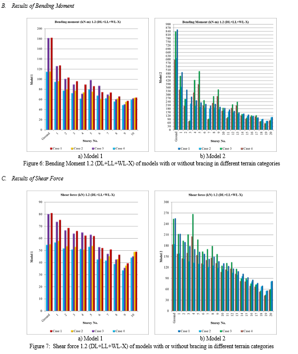
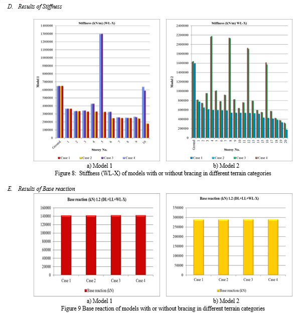
1) Maximum value of joint displacement in 10 floor structure was 49.09mm at top storey this displacement value reduced with application of bracings in terrain category 1 so, value of joint displacement becomes 41.77mm. 2) Maximum value of joint displacement in 10 floor structure was 30.26mm at top storey this displacement value reduced with application of bracings in terrain category 4 so, value of joint displacement becomes 25.68mm. 3) After compare both categories of terrain maximum joint displacement occur in case-1 of 10 floor model and minimum joint displacement occurs in case 4 of 10 floor model. 4) Maximum value of joint displacement in 20 floor structure was 186.70mm at top storey this displacement value reduced with application of bracings in terrain category 1 so, value of joint displacement becomes 121.51mm. 5) Maximum value of joint displacement in 20 floor structure was 144.33mm at top storey this displacement value reduced with application of bracings in terrain category 4 so, value of joint displacement becomes 93.80mm. 6) After compare both categories of terrain maximum joint displacement occur in case-1 of 20 floor model and minimum joint displacement occurs in case 4 of 20 floor model. 7) Maximum value of bending moment in 10 floor structure was 181.77kN-m at ground this bending moment value reduced with application of bracings in terrain category 1 so, value of bending moment becomes 181.28kN-m. 8) Maximum value of bending moment in 10 floor structure was 114.95kN-m at ground this bending moment value reduced with application of bracings in terrain category 4 so, value of bending moment becomes 114.55kN-m. 9) After compare both categories of terrain maximum bending moment occur in case-1 of 10 floor model and minimum bending moment occurs in case 4 of 10 floor model. 10) Maximum value of bending moment in 20 floor structure was 853.61kN-m at ground this bending moment value reduced with application of bracings in terrain category 1 so, value of bending moment becomes 836.78kN-m. 11) Maximum value of bending moment in 20 floor structure was 609.52kN-m at ground this bending moment value reduced with application of bracings in terrain category 4 so, value of bending moment becomes 597.69kN-m. 12) After compare both categories of terrain maximum bending moment occur in case-1 of 20 floor model and minimum bending moment occurs in case 4 of 20 floor model. 13) Maximum value of shear force in 10 floor structure was 80.71kN at ground this shear force value reduced with application of bracings in terrain category 1 so, value of shear force becomes 80.04kN-m. 14) Maximum value of shear force in 10 floor structure was 55.10kN at ground this shear force value reduced with application of bracings in terrain category 4 so, value of shear force becomes 54.54kN. 15) After compare both categories of terrain maximum shear force occur in case-1 of 10 floor model and minimum shear force occurs in case 4 of 10 floor model. 16) Maximum value of shear force in 20 floor structure was 254.72kN at ground this shear force value reduced with application of bracings in terrain category 1 so, value of shear force becomes 253.29kN. 17) Maximum value of shear force in 20 floor structure was 184.04kN at ground this shear force value reduced with application of bracings in terrain category 4 so, value of shear force becomes 182.76kN. 18) After compare both categories of terrain maximum shear force occur in case-1 of 20 floor model and minimum shear force occurs in case 4 of 20 floor model. 19) Maximum value of stiffness in 10 floor structure was 647842.38kN/m at ground this stiffness value increased with application of bracings in terrain category 1 so, value of shear force becomes 648244.82kN/m. 20) Maximum value of stiffness in 10 floor structure was 647166.82kN/m at ground this stiffness value increased with application of bracings in terrain category 4 so, value of shear force becomes 647587.37kN/m. 21) After compare both categories of terrain maximum stiffness occur in case-3 of 10 floor model and minimum stiffness occurs in case 2 of 10 floor model. 22) Maximum value of stiffness in 20 floor structure was 1598882.7kN/m at ground this stiffness value increased with application of bracings in terrain category 1 so, value of stiffness becomes 1640024.6kN/m. 23) Maximum value of stiffness in 20 floor structure was 1587883.59kN/m at ground this stiffness value increased with application of bracings in terrain category 4 so, value of stiffness becomes 1630154.4kN/m. 24) After compare both categories of terrain maximum stiffness occur in case 3 of 20 floor model and minimum stiffness occurs in case 2 of 20 floor model. • Maximum value of base reaction in 10 floor structure was 141955.3kN in case 3 and case4. • Maximum value of base reaction in 20 floor structure was 288906.77kN in case 3 and case4. • After compare both categories of terrain maximum base reaction occur in case 3 and case 4 of 10 and 20 floor model and minimum stiffness occurs in case 1 and case 2 of 10 and 20 floor model.
References
[1] Khan Ahmed Raza, and Anuj Verma, 2021. \"Wind Behavior of Buildings with Shear Wall Using STAAD-Pro.\". [2] K. Suresh Kumar, 2020. Wind loading on tall buildings: Review of Indian Standards and recommended amendments, Journal of Wind Engineering & Industrial Aerodynamics, https://doi.org/10.1016/j.jweia.2020.104240 [3] Minhaj Sania1, G K Shankar Lingegowda, Akshaya Kumar H S, 2019. Effect of Wind Load On Tall Buildings In Different Terrain Category, International Research Journal of Engineering and Technology (IRJET), Volume: 06 Issue: 08 Aug 2019 [4] Prasenjit Sanyal, Sujit Kumar Dalui, 2018. Effects of courtyard and opening on a rectangular plan shaped tall building under wind load, International Journal of Advanced Structural Engineering https://doi.org/10.1007/s40091-018-0190-4 [5] Md Ahesan Md Hameed and Amit Yennawar, 2018. Comparative Study on Wind Load Analysis Using Different Standards -A Review, International Journal of Innovative Research in Science, Engineering and Technology, Vol. 7, Special Issue 3 [6] Er. Mayank Sharma et al. 2018. Critical Appraisal of Gust Factor Method for Wind Loads as Per Indian Standard., International Journal of Engineering Science Invention (IJESI), Volume 7 Issue 4 Ver. II April [7] Shams Ahmed, Prof. S Mandal, 2017. Comparative Study of A long-Wind Response of Major International Codes with Indian Code (IS 875 Part-III (2015)), International Journal of Engineering Research & Technology (IJERT), Vol. 6 Issue 11, November – 2017 [8] Yi Li, Q.S. Lic, Fubin Chend, 2017. Wind tunnel study of wind-induced torques on L-shaped tall buildings, Journal of Wind Engineering and Industrial Aerodynamics, http://dx.doi.org/10.1016/j.jweia.2017.04.013 [9] Yi Li and Qiu-Sheng Li, 2016 Across-wind dynamic loads on L-shaped tall buildings, Wind and Structures, Vol.23, No.5 385-403 [10] Ashwini S Gudur, Prof. H S Vidyadhar, 2016. A Review on Dynamic Wind Analysis of Tall Building Provided with Steel Bracing as Per Proposed draft for Indian Wind code and Effect of Soft Storey, International Research Journal of Engineering and Technology (IRJET), Volume: 03 Issue: 10 [11] Aditya Verma, Ravindra Kumar Goliya, 2016. Comparison of Static Wind Load on High Rise Building According to Different Wind Loading Codes and Standards, International Journal of Engineering Research & Technology (IJERT), Vol. 5 Issue 05 [12] Mohammed Asim Ahmed et al., 2015. Effect of Wind Load on Tall Buildings in Different Terrain Category, International Journal of Research in Engineering and Technology, Volume: 04 Issue: 06 [13] J. A. Amin, A. K. Ahuja, 2014. Characteristics of wind forces and responses of rectangular tall buildings, Int J Adv Struct Eng 6:66 DOI 10.1007/s40091-014-0066-1 [14] Ming Gu, Zhuang-Ning Xie, 2011 Interference effects of two and three super-tall buildings under wind action, The Chinese Society of Theoretical and Applied Mechanics and Springer-Verlag Berlin Heidelberg, DOI 10.1007/s10409-011-0498-9 [15] Z.N. Xie, M. Gu, 2006 Simplified formulas for evaluation of wind-induced interference effects among three tall buildings, Journal of Wind Engineering and Industrial Aerodynamics 95 31–5 [16] M. Gu, Y. Quan, 2004 Across-wind loads of typical tall buildings, Journal of Wind Engineering and Industrial Aerodynamics 92 1147–1165 [17] Sharma, Mayank (2018), “Reliability of Gust Factor Method For Wind Loading As Per Indian Codal Provisions”. Thesis Submitted In Partial Fulfillment Of The Requirement For The Award Of The Degree Of Master Of Technology In Structural Engineering Department Of Civil Engineering, Indo Global College Of Engineering &Technology, Abhipur, Mohali, I.K.Gujral Punjab Technical University, Jalandhar, 2018. [18] Sharma, Shruti, (2002), “Critical Appraisal Of Indian Wind Loading Codal Provisions”, Thesis Submitted To Punjab University Chandigarh, In Partial Fulfillment Of The Requirements For The Award Of Master Of Engineering In Civil Engineering (Structures), Department Of Civil Engineering, Punjab Engineering College, Chandigarh-160012, March 2002. [19] Sharma, V.R., (1993), “Spectral Characteristics and Extreme Value Analysis for Winds in India and Codal Provisions”. Thesis Submitted in Fulfillment of the Requirements for The Degree of Doctor Of Philosophy, Department Of Civil Engineering, I.T.I., Delhi, New Delhi-110016, India, 1993. [20] Sharma, V.R. And Seetharamulu, K. And Chaudhary K. K. (1994),” Extreme Winds and Revised Codal Provisions”, Proceedings, National Seminar On Wind Loads- Codalprovisons, 6-7 April,1994, SREC, Ghaziabad.Pp.4-1 To 4-16. [21] Virpal,Kaur,(2003),”Reliability Of Multi-Storeyed Steel Buildings To Wind Loading As Per Indian Codal Provisions”, Thesis Submitted To The Punjab Agricultural University In Partial Fulfillment Of The Requirement Of The Degree Of Masters Of Technology (Structural Engineering), Department Of Civil Engineering, C.O.A.E., P.A.U. Ludhiana., 2003.
Copyright
Copyright © 2024 Ashwini Arikar, Dr. Tushar G. Shende . This is an open access article distributed under the Creative Commons Attribution License, which permits unrestricted use, distribution, and reproduction in any medium, provided the original work is properly cited.

Download Paper
Paper Id : IJRASET62623
Publish Date : 2024-05-24
ISSN : 2321-9653
Publisher Name : IJRASET
DOI Link : Click Here
 Submit Paper Online

