Ijraset Journal For Research in Applied Science and Engineering Technology
- Home / Ijraset
- On This Page
- Abstract
- Introduction
- Conclusion
- References
- Copyright
Performance Analysis of 8x4 Barrel Shifters in CMOS and FINFET Technology
Authors: Sowmya Sunkara, Rohan Deodurg
DOI Link: https://doi.org/10.22214/ijraset.2024.64448
Certificate: View Certificate
Abstract
Shifters are essential components in digital circuits, enabling data manipulation and routing for a wide range of computational tasks. This study presents a comprehensive performance analysis of 8x4 barrel shifters implemented in two distinct semiconductor technologies: Complementary Metal-Oxide-Semiconductor (CMOS) and FinFET. This study compares and evaluates the important parameters for these shifters at both technological nodes, such as power consumption. Additionally, we examine the effects of scaling on CMOS barrel shifters. Conversely, FinFET technology, recognized for overcoming certain limitations of CMOS, is assessed for its potential to enhance performance while preserving energy efficiency. Through detailed simulation and analysis, this study offers valuable insights into the benefits and limitations of CMOS and FinFET implementations for 8x4 barrel shifters. The circuit is implemented using Cadence Virtuoso and optimized to leverage the unique features and address the limitations of 45nm CMOS and 22nm FinFET technologies. Furthermore, the study offers recommendations for selecting the appropriate technology based on specific performance criteria and application needs. The findings aim to guide future design decisions and improvements in shifter technology.
Introduction
I. INTRODUCTION
The progress in semiconductor technology has revolutionized digital integrated circuits, allowing for the creation of intricate and efficient electronic systems. A crucial factor in this advancement is the barrel shifter, a vital component that allows for the rapid shifting of binary data within digital circuits. As semiconductor engineers strive for greater performance and lower power consumption, they continuously investigate new transistor technologies [1]. This study compares the performance analysis of 8x4 barrel shifters constructed using two primary transistor technologies: Complementary Metal-Oxide-Semiconductor (CMOS) and FinFET, focusing on the 45nm and 22nm process nodes. The Arithmetic Logic Unit (ALU) of a RISC processor performs logical and mathematical functions. While AND, OR, NOT, NAND, NOR, XNOR, and XOR are covered in the logical operations, addition, subtraction, multiplication, and division are covered in the mathematical operations. The RISC processor features register files used to store operands for load/store instructions. The control unit's primary function is to provide control signals that manage the processor's operations, directing the microarchitecture on which operation to execute at any given time. Barrel shifters play a significant role during multiplication operations by shifting and adding partial products [2]. There are four main types of shifters: logical shifter, arithmetic shifter, barrel shifter, and circular shifter.
A barrel shifter is a combinational logic circuit that shifts the data bus contents by a predetermined number of positions to the left or right, as specified by a control word. Typically, when shifting left, the vacated positions are replaced with values from the left, or if no values are available, they are filled with zeros [2]. Alternatively, if no other values are present, the vacated positions may be filled with the value of the most significant bit (MSB). Some shifters rotate the contents of a bus, filling the least significant bits (LSBs) with the previous contents of the MSBs for a left shift and vice versa for a right shift.
Bits can be shifted left or right using a logical shifter, filling the empty positions with zeros. An arithmetic shifter follows the same procedure for left shifting, but when shifting right, the empty position is filled with the sign bit. A barrel shifter rotates bits to the left or right, filling the vacated positions with the bits that were shifted out.
II. LITERATURE SURVEY
The development and execution of an asynchronous bundled- data barrel shifter are examined in this study. It highlights the benefits of using asynchronous circuits and addresses the limitations of traditional barrel shifter systems [1]. The objective of the proposed design is to reduce power consumption and improve performance in electrical equipment. The paper provides a comprehensive analysis of the design plan, including the architecture and components of the barrel shifter. It also contrasts the asynchronous design's performance with the synchronous method, which centers on a floating-point adder.
The design and use of a low-power 8x4 barrel shifter utilizing transmission gate technology are covered in this review paper. At 90 nm technology, simulations and analysis were performed with the Cadence Virtuoso tool [2]. The suggested architecture offers advantages over a barrel shifter constructed with CMOS NAND-based multiplexer technology, especially concerning power consumption, as the article highlights. Barrel shifters can change bits in a single clock cycle; therefore, this design aims to reduce latency and boost efficiency.
The paper discusses the role that modules like shifters, barrel shifters, and arithmetic logic units (ALUs) play on processor performance. It also provides insights into the characteristics and modeling of FinFET transistors and covers the advantages of utilizing FinFET technology in integrated circuits (ICs). The study also discusses the design and evaluation of multiplexers, encoders, memory cells, D-Latch modules, and other components using FinFET technology. It also discusses low- cost security applications, short-channel effects, and gray code converters [3].
For academics and professionals working in the fields of digital electronics and processor design, the document provides useful information overall.
The advantages of asynchronous circuit design compared to synchronous circuit design are examined in this research study. It tackles the problems with synchronous circuits brought on by clock signal constraints and the scalability of technology [4]. The paper emphasizes the demand for faster, more compact, and energy-efficient electronic devices, demonstrating how asynchronous design can fulfill these requirements. It also emphasizes how asynchronous design languages and tools are being developed to enable this methodology. The research also provides insights into the basic operation of the IEEE 754 floating-point number representation format and the functionality of a floating-point adder.
The study also covers optimization techniques and power dissipation studies in digital chip layout design. Static and dynamic power dissipation are among the causes and forms of chip power dissipation that are covered [5]. The study provides insights into power dissipation optimization strategies at many stages of chip design, including the system, algorithm, register, circuit and gate, and layout levels. It also describes ways for analyzing both static and dynamic power dissipation.
The 4-bit barrel shifter is a fundamental component of arithmetic logic units (ALUs), and it is the main subject of the design and analysis covered in this work [6]. A barrel shifter is a logic circuit used for bit indexing, variable-length coding, and arithmetic operations. Multiplexers are commonly utilized, Despite the different methods available for their implementation, a multiplexer uses a control signal to select data by directing one of the inputs to the output. A 2:1 multiplexer is used in a 4-bit barrel shifter. Selection lines, which regulate the direction and amount of rotation, govern the rotation process in a barrel shifter. The paper analyzes the power usage and area efficiency of two design approaches: completely automated and semicustom. The findings show that, with respect to both power and area efficiency, the semicustom design outperforms the fully automated system.
III. METHODOLOGY
In Digital Signal Processors (DSP), an Arithmetic Logic Unit (ALU) uses shift registers to carry out arithmetic operations within a processor. Shift registers can be replaced with high-speed barrel shifters to enhance the performance of ALUs and DSPs. A barrel shifter is a circuit that shifts a bit from the Least Significant Bit (LSB) end to the Most Significant Bit (MSB) end. It serves as a logic circuit for bit indexing, variable-length coding, and arithmetic operations.
There are several ways to integrate barrel shifters, but multiplexers are commonly used. To understand barrel shifters, we must first understand multiplexers. Multiplexers (MUX) are devices that allow the transmission of information from multiple sources to a common destination. They are crucial for boosting the volume of data transmitted through a network within a given time and bandwidth range. For implementing a 4-bit barrel shifter, a 2:1 multiplexer is required. Fig 1 illustrates the block diagram of a 2:1 multiplexer.
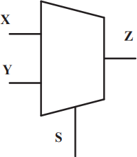
Fig. 1: Block Diagram of 2:1 mutiplexer
The function implemented by MUX is given by,
Z = S? . X + S. Y
Data selectors called multiplexers (MUX) transport one of the input lines to the output in accordance with the control signals from a select line. In the block diagram, X and Y are the input lines, S is the select line, and Z is the output line. The expression S? denotes the inverted form of the select line.
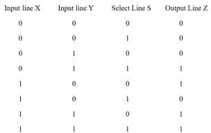
Table 1: Truth table of 2:1 MUX
Various techniques are employed to implement the circuit to enhance the performance of CMOS circuits, such as Transmission Gate Logic and Pass Transistor Logic.
A 2:1 multiplexer is combined in the design of the barrel shifter (MUX). The shifter's output is found via the shift control pins. This specific design is an 8×4-barrel shifter, which means that it produces 4 output bits by shifting 8 input bits according to 5 shift bits. The input bits supplied determine the barrel shifter's output, which varies depending on the active pin of the control shift.
An 8 × 4 barrel shifter is a digital logic circuit capable of shifting binary input data that is 8 bits long left or right by a maximum of 4 places. It is an essential component of digital circuit architecture, commonly used for operations such as data processing, multiplication, and division in microprocessors, arithmetic logic units (ALUs), and other digital systems.
Table 2 explains the operation of the barrel shifter illustrated in Figure 2. The schematic diagram of the 8×4-barrel shifter is built using pass transistors. It features 8 input bits labeled a0 through a7 and 4 output bits labeled b0 through b3. The shifting operation is controlled by five signals, sh0 to sh4, as depicted in Figure 2.
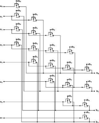
Fig. 2: Schematic diagram of 8×4 barrel shifter
Each transistor in a column receives one control shift signal at its gate terminal. For example, in the first column, the control signal Sh0 is connected to the gate terminals of all transistors. During operation, only one control signal (either sh0 or one of sh1 through sh4) is activated high, while the others are set low.

Table 2: Truth table for the 8x4 barrel shifter
Table 2 illustrates how the output bits respond to the control shift signals. According to Table 2, when sh0 is enabled, the output lines are set as b0 = a0, b1 = a1, b2 = a2, and b3 = a3. In the subsequent clock cycle, when Sh1 is activated, the input bits are shifted right by one position. For an input bit pattern of a0 = 1, a1 = 1, a2 = 0, a3 = 1, a4 = 0, a5 = 0, a6 = 0, a7 = 1 and control bits set to sh0 = 1, sh1 = 0, sh2 = 0, sh3 = 0, sh4 = 0, the output becomes b0 = 1, b1 = 1, b2 = 0, b3 = 1. The Cadence tool has been employed for the design and testing of the barrel shifter.
A. Tool Specification Cadence
Cadence is an Electronic Design Automation (EDA) environment that integrates various applications and tools into a cohesive framework, offering a single platform that supports all phases of IC design and verification. The Cadence toolkit includes several programs tailored for different applications, including chematic drawing, layout, verification, and simulation. These applications can be applied to various computer platforms.
IV. RESULTS
In the following section, the comprehensive results of analysis and simulations for the 4-bit, 8-bit, and 8x4 barrel shifter designs is presented. These results encompass key performance metrics, including speed, power consumption, and area utilization, shedding light on the effectiveness and efficiency of each design within the context of our study.
A. 4-Bit Barrel Shifter
A 4-bit barrel shifter is a digital circuit capable of shifting a 4-bit binary number by a variable number of positions. (ranging from 0 to 3) either to the left or right. It processes 4 input data bits and uses control signals to specify the direction and magnitude of the shift. Below, I'll provide a simplified schematic of a 4-bit barrel shifter to give you an idea of its internal workings.
Inputs:
4-bit Data Input (W0, W1, W2, W3): These are the four data bits that will be shifted.
2-bit Control Input (S1, S0): These control inputs specify the shift direction and distance. The possible combinations are: S1 = 0, S0 = 0: No shift (input data passes through).
S1 = 0, S0 = 1: Right shift by 1 position. S1 = 1, S0 = 0: Left shift by 1 position. S1 = 1, S0 = 1: Left shift by 2 positions. Outputs:
4-bit Data Output (Y0, Y1, Y2, Y3): These are the shifted data bits.
B. 4-Bit Barrel Shifter in CMOS
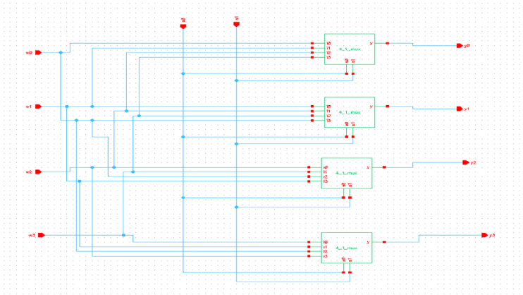
Fig 3: Schematic diagram of 4-bit barrel shifter in cmos
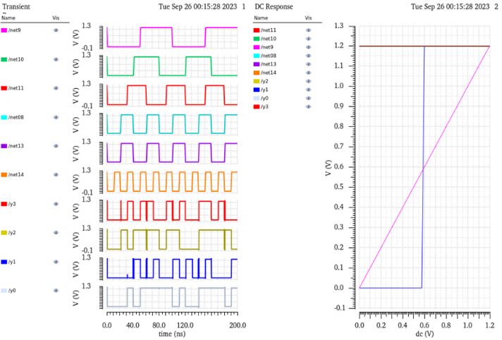
Fig 4: Output response of 4-bit barrel shifter in cmos
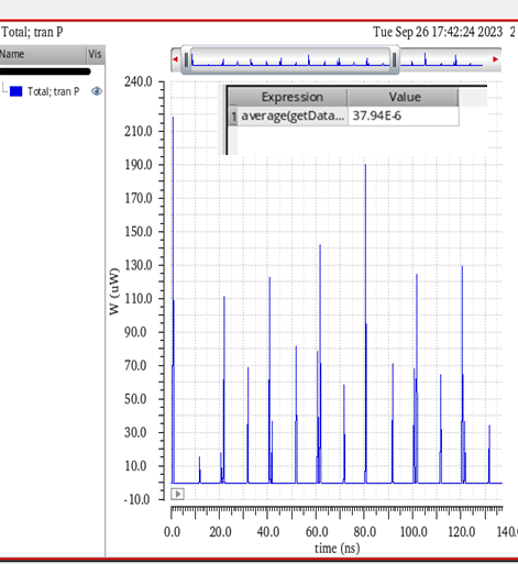
Fig 5: Power analysis of 4-bit barrel shifter in cmos
C. 4-Bit Barrel Shifter in FINFET
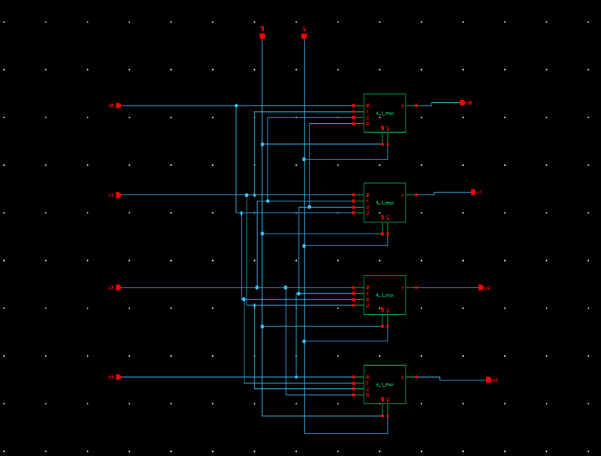
Fig 6: Schematic diagram of 4-bit barrel shifter in Finfet
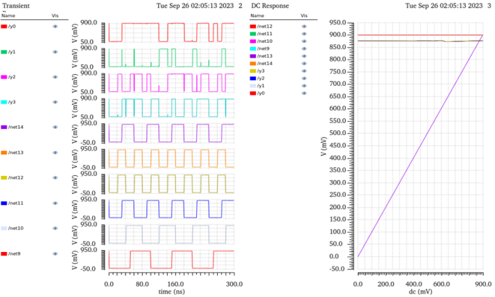
Fig. 7: Output response of 4-bit barrel shifter in Finfet
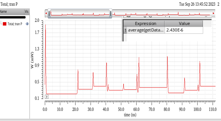
Fig 8: Power analysis of 4-bit barrel shifter in finfet
D. 8-Bit Barrel Shifter
An 8-bit barrel shifter is a digital circuit that allows an 8-bit binary number to be shifted left or right by a configurable number of positions, ranging from 0 to 7. This adaptable part is utilized in digital systems for operations including division, multiplication, and data processing. An description of the 8- bit barrel shifter concept is provided below in simplified form:
Inputs:
8-bit Data Input (I0 to I7): These are the 8 data bits that you want to shift.
3-bit Control Input (S2, S1, S0): These control inputs specify the shift direction and distance. The possible combinations are:
S2 = 0, S1 = 0, S0 = 0: No shift (input data passes through). S2 = 0, S1 = 0, S0 = 1: Right shift by 1 position.
S2 = 0, S1 = 1, S0 = 0: Right shift by 2 positions. S2 = 0, S1 = 1, S0 = 1: Right shift by 3 positions. S2 = 1, S1 = 0, S0 = 0: Right shift by 4 positions. S2 = 1, S1 = 0, S0 = 1: Right shift by 5 positions. S2 = 1, S1 = 1, S0 = 0: Right shift by 6 positions. S2 = 1, S1 = 1, S0 = 1: Right shift by 7 positions. Outputs:
8-bit Data Output (Y0 to Y7): These are the shifted data bits.
E. 8-Bit Barrel Shifter in CMOS
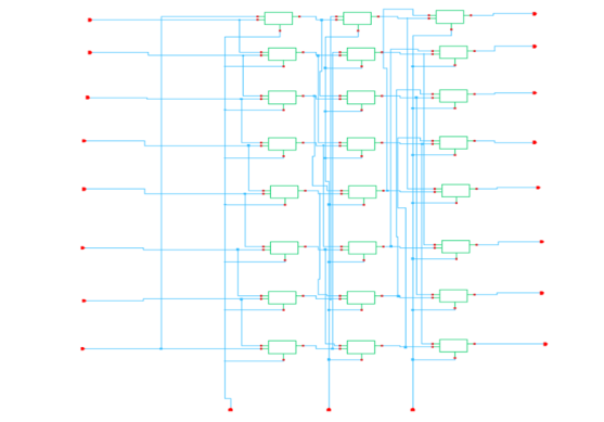
Fig 9: Schematic diagram of 8-bit barrel shifter in cmos
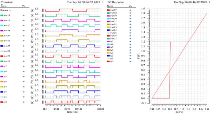
Fig 10: Output response of 8-bit barrel shifter in cmos
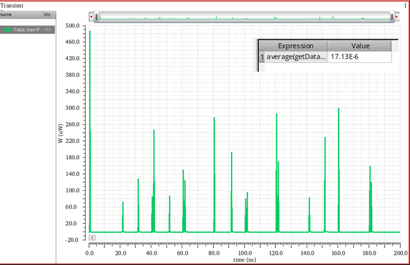
Fig 11: Power analysis of 8-bit barrel shifter in cmos
F. 8-Bit Barrel Shifter in FINFET
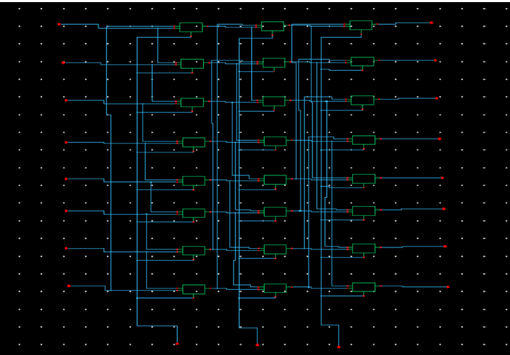
Fig 12: Schematic diagram of 8-bit barrel shifter in finfet
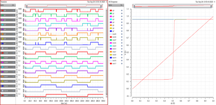
Fig 13: Output response of 8-bit barrel shifter in finfet
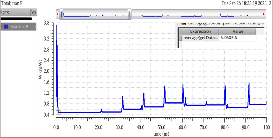
Fig 14: Power analysis of 8-bit barrel shifter in finfet
G. 8 x 4 Barrel Shifter
An 8x4 barrel shifter with 5 control signals is an advanced digital circuit designed to shift an 8-bit binary number by a variable number of positions (up to 4) either to the left or right. The "8 x 4" notation indicates that it operates on 8 data input lines and produces 4 output lines. The term "5 control paths" suggests the existence of five distinct control systems that determine the shifting behavior. This level of flexibility allows for precise and versatile data manipulation. Here is an overview of how such a barrel shifter might work:
Inputs:
8-bit Data Input (I0 to I7): These are the 8 data bits that you want to shift.
Control Paths:
Control Path 1 (S0): Control path 1 may be responsible for selecting specific data bits based on its control signal. It can specify which bits will participate in the shifting operation.
Control Path 2 (S1): Control path 2 could specify the direction of the shift, either left or right.
Control Path 3 (S2): Control path 3 determines the number of shift positions, enabling shifts of 1-bit, 2-bit, 3-bit, or 4-bit.
Control Path 4 (S3): Control path 4 might enable or disable the shifting operation for specific bits.
Control Path 5 (S4): Control path 5 could perform additional operations on the shifted data or control how the shifted data is routed to the outputs.
Outputs:
4-bit Data Output (Y0 to Y3): These are the shifted data bits, which represent the result of the shifting operation after considering all control paths.
H. 8 x 4 Barrel Shifter in CMOS
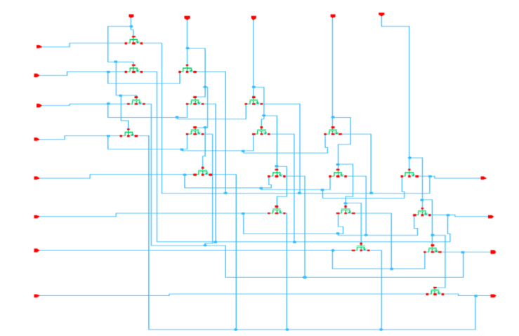
Fig 15: Schematic diagram of 8 x 4-barrel shifter in cmos
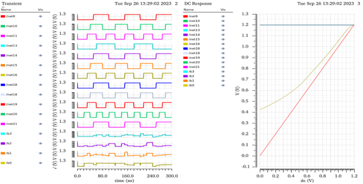
Fig 16: Output response of 8 x 4-bit barrel shifter in cmos
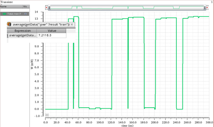
Fig 17: Power analysis of 8 x 4-barrel shifter in cmos
I. 8 x 4 Barrel Shifter in FINFET
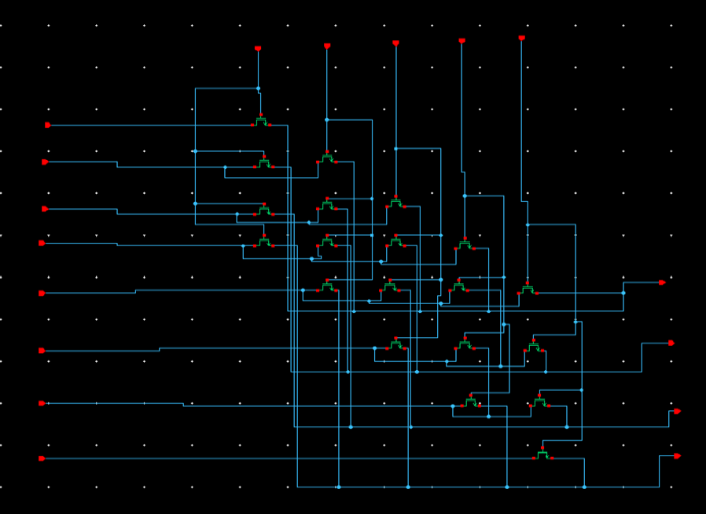
Fig 18: Schematic diagram of 8 x 4-barrel shifter in finfet
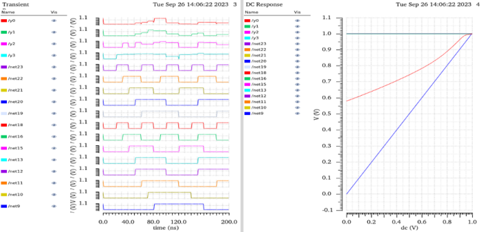
Fig 19: Output response of 8 x 4-bit barrel shifter in finfet
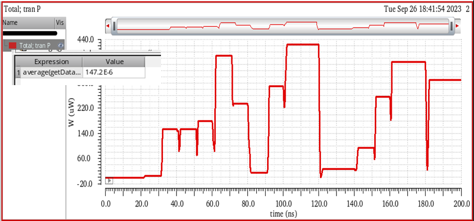
Fig 20: Power analysis of 8 x 4-barrel shifter in finfet
|
Architecture Design |
Avg power (W) CMOS (45nm) |
Avg power (W) Finfet(22nm) |
|
4x4 barrel shifter |
37.94e-6 |
2.43e-6 |
|
8x8 barrel shifter |
17.13e-6 |
5.06e-6 |
|
8x4 barrel shifter |
7.211e-03 |
147.2e-6 |
Table 3: Average Power Analysis of Barrel Shifter
Conclusion
The comparative performance analysis of 8x4 barrel shifters in 45nm CMOS and 22nm FinFET technologies highlights the nuanced trade-offs inherent in selecting the optimal technology for specific digital circuit applications. The investigation revealed that FinFET technology, with its superior control over short-channel effects and reduced leakage currents, delivers notable improvements in both speed and energy efficiency. FinFET is an desirable option for high-performance applications where fast operation and low power consumption are critical due to these characteristics. However, the analysis also underscores the continued relevance of CMOS technology, particularly in scenarios where area efficiency and cost are major considerations. Despite its limitations, CMOS technology still delivers competitive performance and higher integration density, which can be critical in applications with tight area constraints or where design cost-effectiveness is a priority. The study\'s findings add to the current conversation on the strategic selection of semiconductor technology for certain digital components. As semiconductor technology continues to advance, it will be essential to revisit these analyses to incorporate emerging trends and innovations. The results highlight the value of using a tailored strategy when designing digital circuits, where the choice of technology must align with the specific performance, power, and area requirements of the target application. In conclusion, FinFET technology appears to be a superior choice for high-speed, energy-efficient designs, CMOS remains a viable option where integration density and cost are prioritized. Future research should continue to explore these trade-offs, particularly as new technologies emerge, to steer the development of next-generation digital systems.
References
[1] P. Srivastava and E. Chung, \"An Asynchronous Bundled- Data Barrel Shifter Design That Incorporates a Deterministic Completion Detection Technique,\" in IEEE Transactions on Circuits and Systems II: Express Briefs, vol. 69, no. 3, pp. 1667- 1671, March 2022, doi: 10.1109/TCSII.2021.3126853 [2] Ashok Babu, Dr & Nagaraju, V. & Mariserla, Ramya & Vallabhuni, Rajeev, “Realization of 8 x 4 Barrel shifter with 4- bit binary to Gray converter using FinFET for Low Power Digital Applications”,2021 Journal of Physics: Conference Series. 1714 012028, doi: 10.1088/1742-6596/1714/1/012028 [3] P. Tiwari and A. Kumar, \"A 4-bit Barrel Shifter Design using Diverse Logic Style,\" 2021 First International Conference on Advances in Computing and Future Communication Technologies (ICACFCT), Meerut, India, 2021, pp. 131-134, doi: 10.1109/ICACFCT53978.2021.9837367. [4] J. S. D. Vudatha, S. P. Rajeev and B. Sreeja, \"Low Power 90 nm 8 × 4 Pseudo NMOS Barrel Shifter Design,\" 2021 5th International Conference on Electrical, Electronics, Communication, Computer Technologies and Optimization Techniques (ICEECCOT), Mysuru, India, 2021, pp. 649-653, doi: 10.1109/ICEECCOT52851.2021.9708048. [5] Babu, P.A., Nagaraju, V.S., Mariserla, R., & Vallabhuni, R.R.. Realization of 8 x 4 Barrel shifter with 4-bit binary to Gray converter using FinFET for Low Power Digital Applications. Journal of Physics: Conference Series, 1714 , (2021). [6] Srivastava, P.; Chung, E.; Ozana, S. “Asynchronous Floating-Point Adders and Communication Protocols: A Survey”, Electronics 2020, 9,1687. https://doi.org/10.3390/electronics9101687 [7] Y. Zhang, X. Hu, X. Feng, Y. Hu and X. Tang, \"An Analysis of Power Dissipation Analysis and Power Dissipation optimization Methods in Digital Chip Layout Design,\" 2019 IEEE 19th International Conference on Communication Technology (ICCT), Xi\'an, China, 2019, pp. 1468-1471, doi: 10.1109/ICCT46805.2019.8946994. [8] Shah, Sejal et al. “Designing of Low Power Gdi Based 8-Bit Barrel Shifter.” Journal of emerging technologies and innovative research (2018). [9] Anjali Thakur, Dr. Rajesh Mehra, \"CMOS Performance Analysis of 4-bit Barrel Shifter\", International Journal of Emerging Technologies and Innovative Research (www.jetir.org), ISSN:2349-5162, Vol.5, Issue 6, page no.123- 128, June-2018 [10] M. Roopa Nandini and P. Mor, \"A Novel Low Power Dynamic Barrel Shifter using Footed Diode Domino Logic,\" 2017 International Conference on Current Trends in Computer, Electrical, Electronics and Communication (CTCEEC), Mysore, India, 2017, pp. 367-372, doi: 10.1109/CTCEEC.2017.8455194.
Copyright
Copyright © 2024 Sowmya Sunkara, Rohan Deodurg. This is an open access article distributed under the Creative Commons Attribution License, which permits unrestricted use, distribution, and reproduction in any medium, provided the original work is properly cited.

Download Paper
Paper Id : IJRASET64448
Publish Date : 2024-10-03
ISSN : 2321-9653
Publisher Name : IJRASET
DOI Link : Click Here
 Submit Paper Online

