Ijraset Journal For Research in Applied Science and Engineering Technology
- Home / Ijraset
- On This Page
- Abstract
- Introduction
- Conclusion
- References
- Copyright
Power Generation using Speed Breakers and Potholes Detection
Authors: Kalpesh Joshi, Gurmeetsingh Relusinghani, Rohan Khanna, Vivek Raut, Rohan Nalage, Ritik Kumar Singh, Ruturaj Rawate
DOI Link: https://doi.org/10.22214/ijraset.2024.63014
Certificate: View Certificate
Abstract
A large amount of energy is wasted by the vehicles on roads when they apply heavy breaks on speed breakers. This happens due to friction and a high level of energy is produced. Energy can be extracted from the vehicles speed and weight. Another major issue is of major accidents caused by potholes on Indian roads. It is really important to identify these potholes and notify the driver about them to avoid these fatal accidents. Our project is an attempt to solve both these issues an effective, innovative and feasible manner. The domains in our project are energy generation/conservation and image processing. To generate electricity, we want a fast-moving face that can generate electricity. The reciprocating motion of the reducer is converted into rotational motion thanks to the rack and pinion device and a special system called the cylinder. We have developed a smart speed reducer that passes from both sides of the car and generates electricity from there. This system is assembled using all particle board and connecting rods. The system uses a high-speed machine that uses shafts, rollers and electric motors to generate electricity. The roller mechanism is used to return the reducer to its original position. It converts rotational motion into linear motion, but in some cases we use it to convert linear motion into rotational motion. The mechanism is economical and easy to install. With proper planning, we can generate a lot of electricity from traffic. Now let\'s briefly look at the meaning of the hole. Ultrasonic sensors are used to identify holes and bumps and measure their depth and height respectively. This helps people avoid fatal accidents. These two ideas together we solve two problems that people face. Therefore, this project preserves the essence of design thinking.
Introduction
I. INTRODUCTION
India will now be the most populous country in the world. It is a developing country with many connections. He expended a lot of energy to maintain his life on Earth. Roads are the main means of transportation in India today. They carry almost 90% of the passengers in the country. However, most of the roads in India are narrow, congested, poor and their maintenance needs cannot be met. No matter where you live in India, driving is dangerous, distracting and potentially life-threatening. While driving, the speed reducer is only used to reduce the speed of the vehicle; This depends on the material the speed reducer is made of. Sometimes they are made of rubber, sometimes of stone, and sometimes of a combination of different materials such as stone and pavement. Now we can use these reducers to generate electricity. This can be done by introducing the concept of rack and pinion system. The main causes of potholes, especially in India, are heavy rains and poor road construction. This causes a lot of menace and construction problem in the area and it becomes prone to accidents.
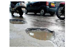
According to the Ministry of Road Transport and Highways' "Traffic Accidents in India 2011" study, a total of 1,42,485 people lost their lives due to serious injuries. Of these, approximately 1.5%, or approximately 2,200 deaths, were due to poor road conditions. That's why we came up with a solution to find these stones by taking photos and warning the driver before a bad accident. In the course of this article, the expansion of the concept of how energy is produced through the use of large cracks and the discovery of pits will be discussed. You may have noticed that this project aims to solve two different problems that people encounter on the road.
II. METHODOLOGY/EXPERIMENTAL
A. Materials/Components/Flowchart/Block Diagram/Theory
For Power Generation
Materials and working
- Dynamo motor
- Gear wheel
- Transistor 2N2222A
- LED bulb
- Resistor 100 Ohm
- Diode
- Battery 1.5 V
- PCB
- Wireless transmitter and receiver Coil
- magnetic wire
- Cell box
- Jack pin
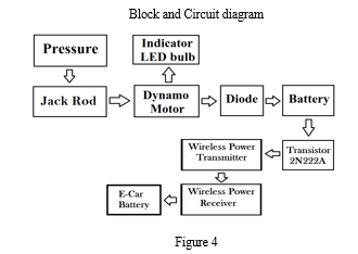
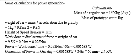
The working principle of this electricity generation is to convert kinetic energy into electrical energy through the use of electricity. This can be done in cases where the application is interrupted. Next, rack and pinion is used to convert kinetic energy into mechanical energy, and then the pinion is connected to the generator to convert the energy into electricity.
a. Speed ??Breaker: It is something that is frequently used in daily life. The product can be made of a mixture of carbon fiber and rubber so that the reducer can withstand the weight of the car, like a box full of equipment. The reducer can be made in such a way that the beginning and end of the slope are made of concrete and cement mixture, and the base is made of the previously mentioned material.
b. Rack and Pinion: This is the simplest type of gear and can be designed according to your own needs. As the name suggests, this type of gears consists of two parts; i.e. the gear which is a spur gear with teeth in one direction only and the second part is the pinion which is a circle which will be on the single Scroll to perform its duties. The balance of these glasses will be vertical.
c. Generator: A generator is a device that converts mechanical energy into electrical energy. In this case, since the operation of the generator remains the same, there will be a pinion on the edge of the generator. The pinion will mesh with the pinion in a rack and pinion arrangement. While the first pinion rotates, the second gear rotates with the motor shaft. This creates an electromagnetic force (EMF) in the generator and produces electricity.
B. Wireless Power Transmission Technology
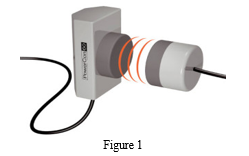
This was first proposed by Nicola Tesla in 1980. There are three main technologies used for wireless power transfer: solar cells, microwave and resonance. In electronics, microwaves are used to transmit electrical energy from the source to the receiver. The WPT principle involves the transfer of inductive electricity from the transmitter to the receiver via an oscillating magnetic field. To obtain the DC current provided by the electrical equipment, specially designed electrical equipment is placed inside the transmitter to convert it into high-frequency AC current. In the transmitter section, alternating current strengthens the copper wire and creates a magnetic field. When the receiver coil is placed near the magnetic field, the magnetic field induces AC current in the receiver coil. Electronic components inside the equipment make it possible to use electricity by converting the current into reverse current.
The Tesla Coil works like this: The large force causes the magnet to break quickly, producing an electric current in two steps. Voltage passes through the air between the two coils, creating a spark in the gap. The principle behind Tesla coils is to achieve a phenomenon called resonance. The Tesla Coil is an electrical transformer created by inventor Nikola Tesla in 1891. It is used to make high voltage, small current and high frequency electronic products. The Tesla coil does more than increase voltage, it also increases frequency. Above you can see a diagram of the different Tesla coils. The capacitor and spark gap together create high voltage pulses that drive the coil.
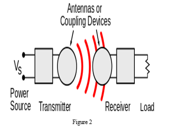
C. These are the Different Wireless Power Technologies
Field regions- Electric and magnetic fields are created by charged particles like electrons. Static charges create an electrostatic field in the space around them. Constant electric current (direct current, DC) creates a static magnetic field around it. The fields described above have energy, but they cannot carry electricity because they are static. But different times can bring energy. Accelerated charges, such as alternating current (AC) electricity in wires, create electric currents that vary magnetically over time and in the space around them. These fields can force the oscillation of electrons in the receiving "antenna", causing them to move. These represent the AC power source for power. The electric and magnetic field oscillating around the charge moving in the antenna can be divided into two regions depending on the Drange distance from the antenna. The lines between regions are somewhat blurred. The fields in these areas have different characteristics and different methods are used to transmit power: approximately 1 wavelength (λ) of the antenna. In this field, the oscillating electric and magnetic fields are separated, and power can be transferred from the electric field by capacitive coupling of metal electrodes (electrostatic induction) or from the magnetic field by the energy of inductive coupling of coils (electromagnetic induction). This field is non-electric, meaning it is located a short distance from the energy emitter. If there is no device to receive or absorb the material to "bind" it within its boundaries, no power will be output from the transmitter. The range of these fields is short and depends on the size and shape of the "antenna" device, usually a coil. The field, and hence the transmitted power, decreases exponentially with distance, so if the distance between two "antennas" Drange is greater than the diameter of the "antenna" Dant, the power will be very low. Therefore, this technology cannot be used to transmit electricity over long distances. Resonances (such as resonant inductive coupling) can increase the coupling of the antenna, making transmission more effective for slightly longer although the field is still distorted. That's why the range of nearby products is usually divided into two groups: short and medium range.
Far field or radiated field - Electric and magnetic fields of approximately 1 wavelength (λ) perpendicular to each other on the antenna and propagating as electromagnetic waves. The amount of power radiated by the antenna in the form of electromagnetic waves depends on the ratio of the antenna mass Dant to the wavelength λ, [30], and this ratio is determined by the frequency: λ = c / f. At low frequency the antenna is smaller than the size of the radio wave (Dant << λ) and the power is very low. Therefore, the above-mentioned close-drive device makes almost weak use of low-frequency radiation in the form of electromagnetic radiation. Antennas similar to wavelength Dant ≈ λ, such as monopoles or dipoles, can radiate good energy, but electromagnetic waves propagate in all directions (omnidirectional), so if the antenna is too far away there is only one small antenna. Value of electromagnetic waves. The radiation will hit it. Therefore these can be used for short-term, weak transmission, but not for long-term transmission.
But unlike fields, electromagnetic waves can be focused into beams by reflection or interference. It can be used to transmit electricity over long distances by using high-speed antennas or optical systems to focus electricity into a narrow beam focused on the receiver. [26] [31] According to the Rayleigh method, the antenna must be larger than the wavelength of the wave used in order to create a narrow beam that will reflect large amounts of energy to distant receivers. : Dant >> λ = c/f. Electronic equipment requires wavelengths in the centimeter region or lower, corresponding to frequencies in the microwave range or higher, above 1 GHz.

Figure 3
D. For Potholes Detection
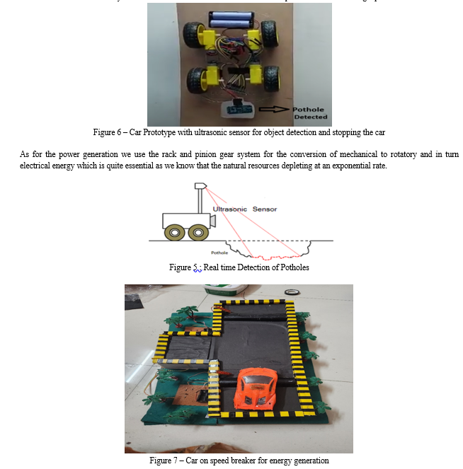
Mozzam et al. have proposed a low-cost model for analyzing 3D pavement distress images. It makes use of a low-cost Kinetic sensor, which gives a clear image of the object. This part of the project mainly focusses on detection of the potholes using image processing that is through an Ultrasonic sensor. To implement the proper functioning the ultrasonic sensor we would require a microcontroller and a device to connect it with. For this, we are using an Arduino UNO board which is one of the best feasible devices to connect with the Ultrasonic sensor. The Arduino requires a power source and it provides the energy for the ultrasonic sensor to work.
The mechanism as to where the ultrasonic sensor is to be attached to the vehicle so that it perfectly senses that a pothole is approaching is based on calculating the distance between the sensor and the road. For knowing that a pothole is approaching beforehand, we need to attach the ultrasonic sensor at tilt of about 15 to 20 degrees.
To do this we have to calculate the hypotenuse distance from the ground. For instance, if the distance between the ground and the sensor is 20cm at an angle of 15 degrees from the ground then we have to code the sensor in a way that it stops the car if it senses that the distance has increased from 20 to about 25. This is because of the fact that a 2 to 5 cm deep pothole won’t affect the car or the driver and won’t cause any accidents. Here is a code that can used for the implementation for sensing a pothole.
III. FUTURE SCOPE
The proposed system takes into account the presence of potholes and bumps. But it does not take into account the fact that authorities regularly fix puddles or bumps. The system can be further improved to take into account the above facts and update the server database accordingly. Google Maps and SATNAV can also be integrated into the planning process to improve user experience. It would also be nice if there was a way to notify the driver of the lake. The future of the project is to improve the safety of speed bumps by using various materials. The generator can also be improved using other types of generators.
IV. ACKNOWLEDGMENT
The success and completion of this project required the guidance and assistance of many people, and we was very fortunate to have that guidance and assistance throughout the completion of the project. All we do is thank you for your guidance and help and we will never forget to thank them. We respect and thank Mr. Kalpesh Joshi for helping us and giving us the opportunity to work on this project. All the support and guidance enabled me to complete the project on time. We are very grateful to him for providing us with such support and guidance even though he was very busy managing the affairs of the College. We thank Mr. Kalpesh Joshi, Project Manager, DESH department and VIT Pune for their guidance and advice during the working of this project.
Conclusion
In conclusion our research is a demonstration of the development of a successful and fully functioning project. The project is really helpful in making a significant impact on the environment and nature. It helps in developing and converting mechanical energy to electrical energy when heavy breaks are applied by different vehicles. This helps in generating energy which gets wasted in the entire world every day on a regular basis. Electricity consumption is increasing day by day and the demand for electricity is also increasing. Therefore, this program can be used in daily life to control electricity demand and reduce the use of other fossil fuels. On the other hand, the same project also focusses and solves another major issue of accidents caused by potholes on the roads of India. We used ana ultrasonic sensor attached to Arduino to detect that there is a gap between the road and the car. This becomes even more significant in India as there are large amounts of potholes on roads due to excessive rains. In a nutshell our project solves two utterly important and different issues that we face in this era.
References
[1] “Implementing intelligent traffic control system for congestion control, ambulance clearance, and stolen vehicle detection,” R. Sundar, S. Hebbar, and V. Golla,IEEE Sensors J., vol. 15, no. 2, pp. 1109–1113, Feb. 2015. [2] “Pothole detection and warning system: Infrastructure support and system design,” S. S. Rode, S. Vijay, P. Goyal, P. Kulkarni, and K. Arya, in Proc. Int. Conf. Electron. Comput. Technol., Feb. 2009, pp. 286–290 [3] “A research of pavement potholes detection based on three-dimensional projection transformation,” H. Youquan, W. Jian, Q. Hanxing, Z. Wei, and X. Jianfang, in Proc. 4th Int. Congr. Image Signal Process. (CISP), Oct. 2011, pp. 1805–1808. [4] “Potholes detection based on SVM in the pavement distress image,” J. Lin and Y. Liu, in Proc. 9th Int. Symp. Distrib. Comput. Appl. Bus. Eng. Sci., Aug. 2010, pp. 544–547. [5] “Non-conventional power plants”, Sharma, P.C., Public Printing Service, New Delhi, 2003. [6] “Effects of speed distribution on the Hormonoise model predictions”, Watts,G., Inter-noise Conference, Prague, 2004. [7] “Bus Drivers Exposure to Mechanical Shocks Due To Speed Bumps”. Dr. Anders Brandt & MSc. John Granlund Swedish Road Administration. Society for Experimental Mechanics, IMAC 25th Conference and Exposition on Structural Dynamics 2008.
Copyright
Copyright © 2024 Kalpesh Joshi, Gurmeetsingh Relusinghani, Rohan Khanna, Vivek Raut, Rohan Nalage, Ritik Kumar Singh, Ruturaj Rawate. This is an open access article distributed under the Creative Commons Attribution License, which permits unrestricted use, distribution, and reproduction in any medium, provided the original work is properly cited.

Download Paper
Paper Id : IJRASET63014
Publish Date : 2024-05-31
ISSN : 2321-9653
Publisher Name : IJRASET
DOI Link : Click Here
 Submit Paper Online

