Ijraset Journal For Research in Applied Science and Engineering Technology
- Home / Ijraset
- On This Page
- Abstract
- Introduction
- Conclusion
- References
- Copyright
Improvement of Power Quality in Grid Connected Wind Energy System
Authors: Sangam Uma Rani, Dr. Sukanth. T
DOI Link: https://doi.org/10.22214/ijraset.2023.54813
Certificate: View Certificate
Abstract
This research covers industrial plant-connected wind turbine system control. An algorithm permits a control structure that uses a four-leg inverter linked to the grid to inject energy and operate as an active power filter, reducing load current disturbances and improving power quality. Algorithms enable this control structure. A four-wire system considers linear and nonlinear three-phase and single-phase loads. The utility-side controller supplies active and reactive power and adjusts for reactive, nonlinear, and unbalanced single- and intra-phase demands during wind turbine connection. Besides providing power, this is done. If there is no wind power, the controller uses the DC-link capacitor and grid-connected power converter to improve power quality. The proposed control structure is based on conservative power theory decompositions, which distinguishes it from previous techniques. This option separates the inverter control power and current references, giving a broad variety of adaptable, selective, and powerful functions. Real-time software benchmarking has tested the recommended control technique for comprehensive real-time implementation. The real-time simulator \\\"FACTS\\\" and the DSP microcontroller test and implement the control strategy in hardware-in-the-loop. These results confirmed our power quality improvement control, allowing us to omit passive filters. This created an electronic smart grid-based control system that was more efficient, adaptive, and reliable.
Introduction
I. INTRODUCTION
The growth in population and rise in energy consumption brought on by industrialization make it more difficult to produce power. By using non-renewable energy sources like coal, diesel, natural gas, and other fossil fuels to produce more energy the old-fashioned way, the environment and people's way of life would be negatively impacted.[1] Since non-renewable resources will eventually run out, we must use our endangered resources to produce new non-renewable energy sources. How quickly these resources are used may have a significant detrimental impact on the environment. The primary contributor to global warming is the burning of non-renewable fuels, which spew hazardous substances into the sky. Due to these sources' impending expiration, their prices are rapidly increasing. As a result, there is a high demand for power. To meet this need, clean electricity must be created using renewable energy sources such as solar, wind, tidal, geothermal, and biomass. These materials are inexpensive and easily accessible. If we possessed the technology, we could solely rely on these sources.
A. Objective of the project
- When we connect a wind turbine to the grid, it may be difficult to discover the underlying causes of power quality concerns since these problems are often tough to overcome. This may make it more difficult for us to find a solution.
- The alternating current line supply that is provided by the utility system should, in a purely technical sense, preferably be a pure sine wave with a fundamental frequency of either 50 or 60 hertz. This would be the ideal situation. This is the perfect scenario.
- As a direct result of this, we are able to arrive at the conclusion that poor power quality may result in a drop in productivity, the malfunctioning or destruction of a wide range of pieces of equipment or domestic appliances, and even pose a threat to human health.
- As a result of this, ensuring that a high level of power quality is continually maintained is of the utmost relevance and should be given the greatest priority. This research offers evidence that power electronic-based power conditioning, which makes use of bespoke power devices such as P-STATCOM, may be utilised efficiently to enhance the quality of power that is delivered to consumers.
- The findings of this study were published in the journal Power Electronics. In addition, the conclusion of this study demonstrates that the improvement is doable, which is very encouraging news.
- This project aims to implement a wind turbine that is connected to a Grid that consists of Distribution generation and P-STATCOM with a backup energy storage system (BESS) in MATLAB, simulate it using the Simpower Systems toolbox, and then verify the results through a variety of case studies that apply non-linear loads and study them in detail. Additionally, this project will also include a backup energy storage system (BESS). In addition to that, the implementation of a backup energy storage system (BESS) on the Grid is another objective of this project.
B. Overview of the project
Renewable energy sources, which have been projected to be a possible alternative energy source, can bring out new challenges when they are connected to the power grid. This is something that has been anticipated. However, due of the dynamic nature of the environment in which they are located, the amount of electricity that can be extracted from renewable sources of energy is subject to a continuous range of fluctuations. In a similar vein, the introduction of wind power into an existing electric grid has the potential to affect the power quality due to the fluctuating nature of wind as well as the relatively innovative sorts of generators that are employed by wind power. In other words, the power quality might be impacted negatively. [6]
The measurements and standards that are carried out in accordance with the regulations that are defined in the standard IEC-61400, which was produced by the International Electrotechnical Commission, are used to assess the performance of the wind turbine and, as a result, the power quality. This evaluation is based on the measurements and standards that are carried out. When a wind turbine is linked to the grid system, several characteristics of power quality, including active power, reactive power, voltage sag, voltage swell, flicker, harmonics, and electrical behaviour of switching operation, are measured. These include: active power, reactive power, voltage sag, voltage swell, flicker, harmonics, and electrical behaviour of switching operation. Measurements of each of these components of power quality are taken in accordance with national and international standards. The findings of the study paper make it abundantly evident that the integration of wind turbines into the grid contributes to a decrease in the overall quality of the power that is produced.
In order to resolve the problems with the power quality, a solution has been proposed that requires attaching a FACTS device known as a "STATIC COMPENSATOR (STATCOM)" to a battery energy storage system (BESS) at a point of common connection. This would allow the problems to be resolved. The technology that allows for the storage of energy in batteries is put into place in order to serve as a backup for the real power source in the event that the wind power experiences fluctuations. The simulation of the FACTS Device (STATCOM) control scheme for the grid-connected wind energy producing system is carried out with the assistance of the power system block set from MATLAB/SIMULINK. The electricity supply is going to benefit from the implementation of this plan. The main supply source is supposed to be relieved of the reactive power demand that the induction generator and the load are putting on it, and the purpose of the recommended plan is to find a way to make that happen. On the basis of the data that we have accumulated, we have validated the practicability and utility of the approach for the applications that were taken into account.
The STATCOM, which is a compensating device, is in charge of controlling the flow of active and reactive power that is required by the Induction Generator of the wind turbine. It is now seeing a spike in popularity in these contemporary times due to its distinctive style, and there is solid justification for this development.
exceptional features such as the fact that it has a quick response time, that it is suitable for dynamic load response or voltage regulation and automation needs, that it can provide both leading and lagging VARS to correct voltage surges or sags caused by reactive power demands, that pulse STATCOM can be applied on a wide range of distribution and transmission voltage, and that its overload capability provides reserve energy for transients from the BESS are just some of the exceptional features.
The pulse STATCOM is controlled by the PI controller, which is the component in question. In this article, not only is the whole history of compensating devices covered but also the power electronic applications that have been used in compensating devices. In addition to this, a comprehensive discussion is also included on the STATCOM modelling method for compensation.
The theoretical analyses of the several different kinds of control strategies that may be used for the control of STATCOM are detailed here, together with the required block diagrams and the necessary transformations.
Certain conclusions are formed based on the simulated results that were attained, and this analysis also includes an investigation into the potentially expanded scope of the project in the future.
II. DISTRIBUTION GENERATION
The vast bulk of both the production and supply of electric power has traditionally originated from centralized and regulated electric utilities. This has been the case for all of the history of the industry. Distributed generation, sometimes abbreviated as DG, is a power generation method that was developed in response to the growing need for electric power. Customers may have access to additional capacity via this kind of output, which may serve to augment the energy that is supplied by the central power plant. These are relatively small power generators that may be set up anywhere along the length of the distribution system. They can be located at the consumer end of the system or anywhere else along its length. Customers of the utility company, as well as the utility company itself, could stand to gain in certain ways from DG. The many benefits that are associated with DG have piqued the curiosity of consumers, and this is one reason why DG has gained popularity. These advantages include cost savings during peak demand charges, enhanced power quality, and higher energy efficiency. Some of these benefits are listed below. Another benefit for the utility companies comes in the form of the elimination of the expenditures that are often connected with the installation of new transmission and distribution lines.

In the course of the last 10 years, there has been a growth in interest in the hypothesis that the grid may be powered by a myriad of small-scale energy sources. This gain in interest has been accompanied by an increase in research on the topic. First and foremost, this interest was sparked by the development of new technologies as well as by altering patterns in both economic and legal settings. These were the key factors that led to the rise of this interest. The International Energy Agency (IEA) identifies five primary contributors to this progression as having a significant impact on this development. These causes include improvements in technology for distributed generation, limits on the installation of new transmission lines, a rise in consumer demand for power that is extremely dependable, the liberalisation of the market for electricity, and worries about climate change. In view of the fact that it is very doubtful that distributed generation would be able to avoid the building of new transmission lines, the benefits that seem to be the most considerable are specifically those that belong to the last two points. This is because it is highly unusual that distributed generation would be able to prevent the construction of new transmission lines. At the absolute minimum, connection to the grid is required so that it may act as a secondary source of power if necessary. [18] Within the framework of a market that has been liberalised, the process of distributed generation offers participants in the market a number of benefits that they would not otherwise have access to. Customers often look for electrical services that are tailored to meet their requirements in the best possible way. Distributed generation technologies may be of assistance to energy suppliers in meeting the needs of their clients by supplying them with the kind of power service that is most suitable for them. Customers put differing degrees of attention on the many aspects of the electrical energy supply that may be distinguished by their names. Distributed generators (DG) offer a number of attractive benefits over the majority of different types of larger central power plants, one of the most fascinating of which is their flexibility, which makes it possible for market actors to adapt to evolving market conditions. Distributed generators (DG) also have a number of other appealing features. This is a distinct possibility on account of DG's small proportions in addition to the reduced fabrication lead times.
III. WIND POWER GENERATION
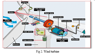
Wind power may be described as the use of wind turbines in order to convert the kinetic energy of wind into a form that is more easily consumable, such as electricity. This is an example of how wind power is used. Windmills are machines that directly convert the kinetic energy of wind into usable mechanical work, such as the grinding of grain or the pumping of water. They may be found in many countries across the world. Because wind energy is abundant, renewable, broadly distributed, and environmentally friendly, switching from the production of electricity using fossil fuels to the production of electricity using wind energy results in a reduction in greenhouse gas emissions. The potential for harvesting wind energy exists in a wide variety of settings. When just a small part of total demand is met by wind power, the variable nature of wind seldom results in issues that are difficult to manage. This is because wind power only meets a tiny fraction of total demand. On the other side, when wind is exploited to provide a significant portion of demand, additional expenditures are incurred as a direct result of this utilisation. [10]
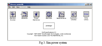
IV. IMPLEMENTATION IN MATLAB (SIMULINK)
The programmer’s entire name is likewise named Matrix Laboratory; the term "Matrix Laboratory" is just a shortened version of the programme's full name. Matrix Laboratory is the full name of the programmed that you are using. The MATLAB software package was developed so that high-performance numerical calculation and visualization could be accomplished. This phrase was derived from an acronym that stands for "matrix laboratory." It offers a straightforward environment that is brimming with hundreds of pre-programmed options for carrying out technical computations, graphical representations, and animations. In addition to that, it offers consumers a friendly and helpful environment to work in.
The computer programme known as MATLAB is the tool of choice for those who work in the field of electrical engineering. This is because it has great visual qualities in addition to a wide variety of analytical applications, adaptability, and reliability. Another reason for this is that it is very adaptable.
The most impressive characteristic of MATLAB is the ease with which it can accommodate the addition of brand-new capabilities. The fact that it comes pre-installed with its very own high-level programming language is what makes this possibility a reality It is possible to rely on MATLAB's interactive environment, which comes equipped with hundreds of pre-programmed mathematical functions, to provide correct results. Calculations in linear algebra, data analysis, signal processing, optimization, numerical solution of ODEs, quadrature, and a wide range of other sorts of scientific calculations are all capable of being completed with the aid of the built-in functions that are offered by this application. Additional applications of the technique include signal processing, optimization, and optimization, respectively.
- The development and refinement of algorithmic processes and protocols When it comes to the process of product development, modelling, simulation, and prototyping are all extremely significant processes that need to be followed.
- An examination of the data, the techniques that were used to process it, and the ways in which the results of those operations were presented
- visuals that may be used in a range of different scientific and technological settings.
- Creating graphical user interfaces, often known as GUIs, is a step that is frequently included in the process of designing programmes.
B. Distribution Generator
Provides a view of the synchronous alternator that is used in the hydraulic power plant. You can find this alternator shown here. The component known as the hydraulic turbine governor (HTG) is responsible for regulating the amount of power that is sent into the alternator. The poles get their shock of energy from a process known as excitation. Because we are replicating the process of renewing the three-phase power output here in the simulation, we are utilising the power output as an input to the hydraulic turbine governor. This allows us to properly simulate the process. Both the voltage at the direct axis and the voltage at the quadrature axis are sent back into the excitation system so that it can generate the required dc voltage. This allows the excitation system to function properly. The output voltage is 13.8 kilovolts, and the output current is rated at 200 megavolt-amperes. A step-up transformer is used so that the voltage may be increased all the way to 230 kilovolts. Shunt loads' only function in this particular scenario is to prevent the error that would be brought on by connecting the machine's transformer and alternator in series, which is the only reason why they are employed. Before being connected to the grid, the output ports A, B, and C are sent via a step-down transformer so that the voltage may be reduced to 415 volts, which is the standard grid voltage.

B. Wind Power Generation
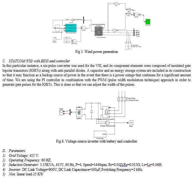
The generation of energy by means of a wind turbine that has both a pitch control and an induction generator We have decided to employ an induction generator as our main generating unit since, in contrast to other kinds of generators, it provides a greater number of advantages, including the fact that it is simpler to operate and requires less money to purchase. The pitch angle controller gives the user the ability to modify the angle of the turbine blade in such a way that the speed of rotation is kept at a constant level regardless of the speed of the wind. In addition to this, while the IM is operating as a generator, it is the parallel capacitive bank's responsibility to provide reactive power to the IM. In this section of the study, the per-unit figures that were displayed in figure 6.9 for the closed loop were the primary focus of our attention. At each sample time interval, the rms values of the current and voltage that are being produced are collected, the power that is being generated is calculated, and the wave form is traced in the scope. These measurements are carried out in order. In order to assign the wind velocity to three unique states, FIG makes use of a timer. These states will all become linear after particular loop operations have been carried out.
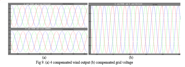
Conclusion
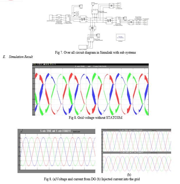
The FACTS device (STATCOM)-based control approach that we present in this paper is intended to improve power quality in grid-connected wind generating systems that also incorporate nonlinear loads. We came up with the idea for this design. This article discusses the issues with power quality as well as the consequences these issues have on both the customers of the electric utility and the company itself. In order to maintain consistent power quality, it is necessary to recreate, in MATLAB or Simulink, the operation of the control system that was developed for the STATCOM. It is able to get rid of any harmonic components that might be in the load current at the same time. Because it is able to retain the source voltage and current in phase as well as support the reactive power demand for the wind generator and load at PCC in the grid system, it allows the option of boosting the transmission line\\\'s factor of utilisation. This is because of its capacity to keep the source voltage and current in phase. As a result, the combined wind generation and FACTS device with BESS have shown the exceptional performance required to maintain the voltage profile in accordance with the requirements. As a consequence of this, the power quality standards of the grid-connected system are met by the technique that has been provided, which also prevents distortion and harmonics from occurring in the grid voltage.
References
[1] Yuvaraj and Pratheep Raj, Anna University of Technology “Power Quality Improvement for Grid Connected Wind Energy System using FACTS device”, ,” IEEE Trans. on E. Conv., vol. 23, no. 1, pp. 163–169, 2008. [2] R. Billinton and Y. Gao, “Multistate wind Energy conversion system models for adequacy assessment of generating systems incorporating wind energy,” IEEE Trans. on E. Conv., vol. 23, no. 1, pp. 163–169, 2008. [3] J. Manel Carrasco, “Power electronic system for grid integration of renewable energy source: A survey,” IEEE Trans. Ind. Electron., vol. 53, no. 4, pp. 1002–1014, 2006. [4] M. Tsili and S. Papathanassiou, “A review of grid code technology requirements for wind turbine,” Proc. IET Renew.power gen., vol. 3, pp. 308–332, 2009. [5] J. J. Gutierrez, J. Ruiz, L. Leturiondo, and A. Lazkano, “Flicker measurement system for [6] wind turbine certification,” IEEE Trans. Instrum. Meas., vol. 58, no. 2, pp. 375–382, Feb. 2009. [7] Indian Wind Grid Code Draft report on, Jul. 2009, pp. 15–18, C-NET. [8] C. Han, A. Q. Huang, M. Baran, S. Bhattacharya, and W. Litzenberger, “STATCOM impact study on the integration of a large wind farm into a weak loop power system,” IEEE Trans. Energy Conv., vol. 23, no. 1, pp. 226–232, Mar. 2008. [9] F. Zhou, G. Joos, and C. Abhey, “Voltage stability in weak connection wind farm,” in IEEE PES Gen. Meeting, 2005, vol. 2, pp. 1483–1488. [10] A. Mortezaei, C. Lute, M. G. Simões, F. P. Marafão, and A. Boglia, “PQ , DQ and CPT Control Methods for Shunt Active Compensators – A Comparative Study,” Energy Convers. Congr. Expo., pp. 2994–3001, 2014. [11] A. Mortezaei, M. G. Simoes, T.D. Busarello, and A. Al Durra, “Multifunctional Strategy for Four-leg Grid-tied DG Inverters in Three phase Four-wire Systems under Symmetrical and Asymmetrical Voltage Conditions”, in Proc. 12th IEEE/IAS Int. Conf. Ind. Appl., Curitiba, Brazil, Nov. 2016, pp. 1–8. [12] V. Khadkikar, A. Chandra, and B. Singh, “Digital signal processor implementation and performance evaluation of split capacitor, four-leg and three H-bridge-based three-phase four-wire shunt active filters”, IET Power Electron., vol. 4, no. 4, pp. 463–470, 2011. [13] Z. Liu, J. Liu, and J. Li, “Modelling, analysis, and mitigation of load neutral point voltage for three-phase four-leg inverter”, IEEE Trans. Ind. Electron., vol. 60, no. 5, pp. 2010–2021, 2013. [14] L.B. Garcia Campanhol, S.A. Oliveira da Silva, and A. Goedtel, “Application of shunt active power filter for harmonic reduction and reactive power compensation in three-phase four-wire systems”, IET Power Electron., vol. 7, no. 11, pp. 2825-2836, 2014.
Copyright
Copyright © 2023 Sangam Uma Rani, Dr. Sukanth. T. This is an open access article distributed under the Creative Commons Attribution License, which permits unrestricted use, distribution, and reproduction in any medium, provided the original work is properly cited.

Download Paper
Paper Id : IJRASET54813
Publish Date : 2023-07-16
ISSN : 2321-9653
Publisher Name : IJRASET
DOI Link : Click Here
 Submit Paper Online

