Ijraset Journal For Research in Applied Science and Engineering Technology
- Home / Ijraset
- On This Page
- Abstract
- Introduction
- Conclusion
- References
- Copyright
Q-EDR Hybrid Boost Converter Operation For High Gain With Low Device Stress
Authors: K. Threyini, P. Bhavana, S. Vinay Kumar
DOI Link: https://doi.org/10.22214/ijraset.2024.63869
Certificate: View Certificate
Abstract
The hybrid continuous-discontinuous mode (CCM-DCM) operation of non-isolated systems is proposed in this paper. boost converter with quadratic extended duty ratio (Q-EDR) for applications with high gain and low power. The inductors at the input while the EDR was in continuous conduction mode (CCM) The mode of operation of stage inductors is discontinuous conduction. (DCM) in order to reap the advantages of CCM and DCM operation. Interleaving\'s ripple in the low input current and low voltage The EDR stage switches\' stress remains. With what is being half and half method of activity, the inductance worth of EDR stage significant decrease in the inductor. an additional decrease in switch voltage is accomplished during turn-on progress in the proposed activity, prompting huge decrease thus on exchanging losses. This lets the converter run at higher switching speeds. frequency, thereby reducing EDR inductors\' size by 45 percent in this instance an experiment confirms the proposed idea. Simulink prototype for a two-phase Q-EDR operating at 30 V-40 V to 400 V output, a gain of more than 12 at duty close to 0.54. The converter has a peak efficiency of 95.5 percent. at a switching frequency of 135 kHz and 300 W for all silicon switches.
Introduction
I. INTRODUCTION
Non-confined high increase DC help converters have been getting some decent momentum for sun powered and energy component applications as they can accomplish higher effectiveness with more modest size [1]-[3]. Most of the business PV microinverters require a lift converter to move forward the low voltage from PV boards (under 40 V) of the DC connect voltage of 400 V [4], [5], accentuating the need of a high increase converter. As of late numerous geographies are introduced in the writing which utilize a mix of exchanged capacitors [6], [7], exchanged inductor [8] and voltage multiplier (VM) cells [9] to accomplish the high voltage gain. Aside from these, DCM activity of a few converters has been investigated in writing as it gives higher addition at low obligation, decreases the inductor size and decreases the exchanging misfortunes [10]-[12]. Conventional quadratic boost converter (QBC) is a solitary switch geography which accomplishes quadratic voltage gain at the cost of significant conduction loss and high device stress [13]. QBC's operation and analysis in discontinuous mode (DCM) is presented in [11], which introduces four distinct modes. Among the four modes, DCL2 mode (which works as it were internal inductor in DCM) is guaranteed as a valuable mode for better execution analyzed than CCM. Conductance crucial mode (CRM) activity of QBC is introduced in [14], which works under fluctuating recurrence range with just transitional stage inductors in CRM, while input inductor actually running under CCM keeping up with lower input current wave and simultaneously achieving delicate exchanging activity. A fuel source in [15], application-based QBC is proposed, while another Between the junction of the intermediate capacitor and the high voltage side of the output, a storage element capacitor is added. It looks into the QBC's operation under various DCM variants in terms of operations of the inductor A boost converter with high gain and semi quadratics is presented in [16], where the second stage QBC inductor is substituted for a coupled inductor in order to achieve high gain in a semi quadratic form This gain is greatly influenced by the number of the coupled inductor's turns and its application is challenging. With cuk, a cascaded version of quadratic boost converter and voltage multiplier cells have been examined in [17], [18].
An interleaved inductor, exchanged capacitor coordinated converter is proposed in [19]-[20], to highlight high move forward voltage transformation proportion with a moderate obligation cycle. The converter geography is presented as extended duty ratio (EDR) support converter which can achieve high increase with lower current and across all devices, voltage stress. To broaden the voltage, gain in addition, a cascaded quadratic configuration with an EDR stage (QEDR) is suggested in [21], which is simple to achieve. super high increase with moderate obligation levels, while holding the benefits of using the EDR converter. The operation of DCM the in-depth analysis of the EDR converter and its benefits has been introduced in [12]. This inspires towards the recent investigation into the hybrid operational mode EDR quadratic DC-DC converters were proposed.
In this paper, a hybrid CCM-DCM activity of the Q-EDR architecture is suggested in which EDR inductors function in DCM while input inductors work in CCM. With this suggested methodology, the advantages of DCM in the quadratic stage and CCM in realized are the EDR stages. Higher gain over CCM, reduced device stress, low input current ripple, decreased switching loss, and nearly equal current stress in the switches are only a few of the main advantages of the suggested hybrid method. This plan lowers switch turn-on losses by clamping the switching node voltage to an intermediate capacitor voltage just prior to the switch turn-on transition. Additionally, compared to the CCM scenario, the DCM mode of operation for the EDR stage permits a considerable inductor volume decrease while maintaining extremely low input current ripple. The suggested procedure is confirmed.
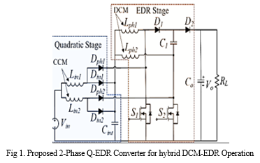
II. DISCONTINUOUS MODES OF OPERATION OF Q- EDR
The quadratic converter in CCM is cascaded with EDR to yield Q-EDR topology; the details of this converter operation have already been covered in [21]. A two-stage Q-EDR converter Fig. 1 depicts an EDR converter with a 2-phase EDR stage and an interleaved quadratic stage. The converter is run at a duty of 0.5 and above, with the switches S1 and S2 phase-shifted 180 degrees. It has lower device voltage stress and intrinsic current sharing between the inductors in the EDR stage, just as the EDR converter. The converter can function in three different modes, which are explained below, each of which corresponds to the discontinuous conduction operation of the two sets of inductors (Lin and Ulph).
A. DCM-IN: Input Inductors in DCM
Only the input inductors (Lin1 and Lin2) in this instance are in the discontinuous conduction state. The converter functions and the EDR stage inductors run continuously in this instance, partial DCM. The boundary condition (1) between Lin's CCM and DCM may be obtained in a manner akin to that of traditional QBC. In this case, D′ is defined as the obligation D's complementary (D′ = 1−D). When comparing a 2-phase Q-EDR to a traditional quadratic boost converter, a factor of 2 in (1) is seen, which is in line with the Q-EDR's voltage gain expression in CCM. The critical value of the dimensionless parameter K1 for DCM operation may be found in (1). The worth of K1 is depending on the input inductance value, load resistor and converter switching frequency.

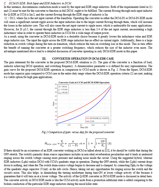
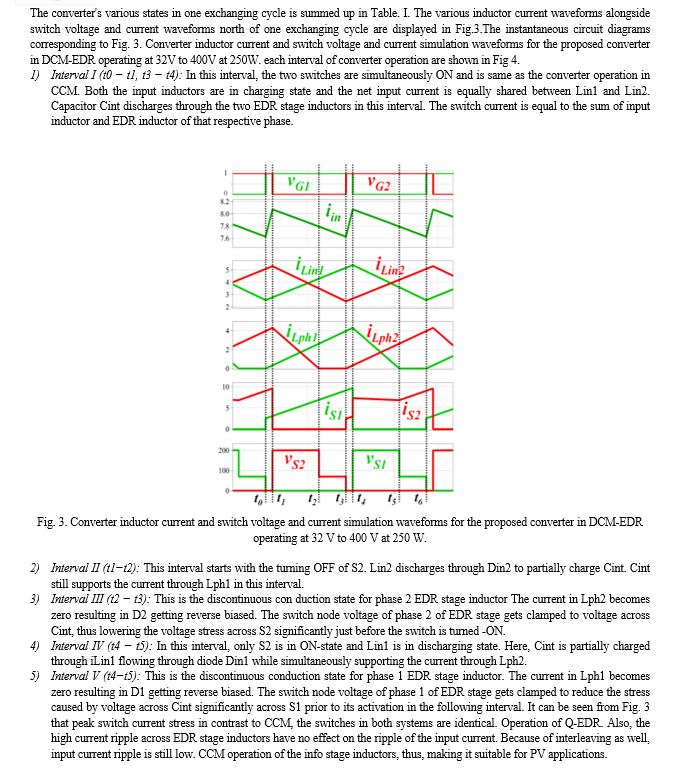
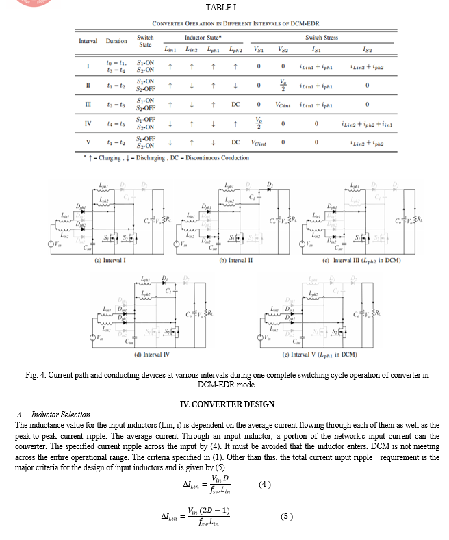
Conclusion
The QEDR converter\'s various discontinuous operation modes are discussed, and the most advantageous hybrid mode DCM-EDR is chosen based on its numerous benefits. The converter\'s operation in DCM-EDR mode is thoroughly discussed. With the proposed DCM-EDR mode, the converter can achieve voltage gains greater than 12 at duty ratios close to 0.54. Additionally, switch turn on losses are reduced as the turn-on switch voltage drops to one fifth of the output voltage. This also makes it possible to operate at a higher switching frequency, which reduces the inductance value even further. When compared to CCM, the DCM-EDR case\'s EDR inductor size decreases by 45 percent, while the inductance itself decreases by 80 percent. A hardware prototype with a 300 W output and a voltage range of 30 V to 40 V and 400 V is used to test the proposed converter\'s operation. A misfortune breakdown with examination of the traditional CCM and DCM-EDR mode is introduced to feature the benefits of the proposed conspire. When all of the silicon switches are in use, the converter can operate at 300 W with a peak efficiency of 95.5 percent. Consequently, we use this hybrid CCM-DCM operation of a quadratic boost converter with an extended duty ratio to achieve high gain at low device stress.
References
[1] J. Carrasco, L. Franquelo, J. Bialasiewicz, E. Galvan, R. PortilloGuisado, M. Prats, J. Leon, and N. Moreno-Alfonso, “Power-electronic systems for the grid integration of renewable energy sources: A survey,” IEEE Transactions on Industrial Electronics, vol. 53, no. 4, pp. 1002–1016, 2006. [2] F. L. Tofoli, D. d. C. Pereira, W. Josias de Paula, and D. d. S. Oliveira Junior, “Survey on non-isolated high-voltage step-up dc–dc topologies based on the boost converter,” IET Power Electronics, vol. 8, no. 10, pp. 2044–2057, 2015. [3] W. Li and X. He, “Review of non-isolated high-step-up dc/dc converters in photovoltaic grid-connected applications,” IEEE Transactions on Industrial Electronics, vol. 58, no. 4, pp. 1239–1250, 2011. [4] IQ 7 Micro and IQ 7+ Micro, Enphase Energy, Aug. 2020, rev1.0. [5] QS1 Microinverter, APsystems, Aug. 2021, rev3.1. [6] M. D. Seeman and S. R. Sanders, “Analysis and optimization of switched-capacitor dc–dc converters,” IEEE Transactions on Power Electronics, vol. 23, no. 2, pp. 841–851, 2008. [7] B. Axelrod, Y. Berkovich, and A. Ioinovici, “Switched capacitor/switched-inductor structures for getting transformerless hybrid dc–dc pwm converters,” IEEE Transactions on Circuits and Systems I: Regular Papers, vol. 55, no. 2, pp. 687–696, 2008. [8] O. Abdel-Rahim, M. Orabi, E. Abdelkarim, M. Ahmed, and M. Z. Youssef, “Switched inductor boost converter for pv applications,” in 2012 Twenty-Seventh Annual IEEE Applied Power Electronics Conference and Exposition (APEC), 2012, pp. 2100–2106. [9] L. Schmitz, D. C. Martins, and R. F. Coelho, “Comprehensive conception of high step-up dc–dc converters with coupled inductor and voltage multipliers techniques,” IEEE Transactions on Circuits and Systems I: Regular Papers, vol. 67, no. 6, pp. 2140–2151, 2020. [10] D.-H. Kim, G.-Y. Choe, and B.-K. Lee, “Dcm analysis and inductance design method of interleaved boost converters,” IEEE Transactions on Power Electronics, vol. 28, no. 10, pp. 4700–4711, 2013. [11] O. Lopez-Santos, L. Martinez-Salamero, G. Garcia, H. Valderrama Blavi, and D. A. Zambrano-Prada, “Steady-state analysis of inductor conduction modes in the quadratic boost converter,”IEEE Transactions on Power Electronics, vol. 32, no. 3, pp. 2253–2264, 2017. [12] J. Roy, A. Gupta, and R. Ayyanar, “Discontinuous conduction mode analysis of high gain extended-duty-ratio boost converter,” IEEE Open Journal of the Industrial Electronics Society, vol. 2, pp. 372–387, 2021. [13] D. Maksimovic and S. Cuk, “Switching converters with wide dc conversion range,” IEEE Transactions on Power Electronics, vol. 6, no. 1, pp. 151–157, 1991. [14] N. Korada and R. Ayyanar, “New crm topology for zero voltage switching in quadratic high gain boost converter,” in 2020 IEEE Energy Conversion Congress and Exposition (ECCE), 2020, pp. 4794–4801. [15] M. A. B. Kumar and V. Krishnasamy, “Quadratic boost converter with less input current ripple and rear end capacitor voltage stress for renewable energy applications,” IEEE Journal of Emerging and Selected Topics in Power Electronics, pp. 1–1, 2021. [16] S. Hasanpour, Y. P. Siwakoti, A. Mostaan, and F. Blaabjerg, “New semiquadratic high step-up dc/dc converter for renewable energy applications,” IEEE Transactions on Power Electronics, vol. 36, no. 1, pp.433–446, 2021. [17] V. F. Pires, A. Cordeiro, D. Foito, and J. F. Silva, “High step-up dc–dc converter for fuel cell vehicles based on merged quadratic boostCuk,” IEEE Transactions on Vehicular Technology, vol. 68, no. 8, pp. 7521– 7530, 2019. [18] J. Leyva-Ramos, R. Mota-Varona, M. G. Ortiz-Lopez, L. H. DiazSaldierna, and D. Langarica-Cordoba, “Control strategy of a quadratic boost converter with voltage multiplier cell for high-voltage gain,” IEEE Journal of Emerging and Selected Topics in Power Electronics, vol. 5, no. 4, pp. 1761–1770, 2017. [19] J. Roy and R. Ayyanar, “Gan based high gain non-isolated dc-dc stage of microinverter with extended-duty-ratio boost,” in 2016 IEEE Energy Conversion Congress and Exposition (ECCE), 2016, pp. 1–8. [20] J. Roy and R. Ayyanar, “Sensor-less current sharing over wide operating range for extended-duty-ratio boost converter,” IEEE Transactions on Power Electronics, vol. 32, no. 11, pp. 8763–8777, 2017. [21] A. Gupta, N. Korada, and R. Ayyanar, “Quadratic extended-duty-ratio boost converter for ultra-high gain application with low device stress,” in 2021 IEEE Applied Power Electronics Conference and Exposition (APEC), 2021, pp. 1796–1802.
Copyright
Copyright © 2024 K. Threyini, P. Bhavana, S. Vinay Kumar. This is an open access article distributed under the Creative Commons Attribution License, which permits unrestricted use, distribution, and reproduction in any medium, provided the original work is properly cited.

Download Paper
Paper Id : IJRASET63869
Publish Date : 2024-08-03
ISSN : 2321-9653
Publisher Name : IJRASET
DOI Link : Click Here
 Submit Paper Online

