Ijraset Journal For Research in Applied Science and Engineering Technology
- Home / Ijraset
- On This Page
- Abstract
- Introduction
- Conclusion
- References
- Copyright
Rapid Investment Casting: Towards Rapid Die Development
Authors: Ahmed Khan, Muhammad Sajid, Ahmad Wasim, Salman Hussain, Mirza Jahanzaib, Hussain Saeed Tunbell, Nikhil Hombegowda
DOI Link: https://doi.org/10.22214/ijraset.2024.58208
Certificate: View Certificate
Abstract
Presently the cost of investment casting via wax patterns is an expensive endeavor. Its costs are only justified if the end product is to be produced in high volumes, however for customized products or small Industries, the costs are not viable. In Pakistan, die manufacturing is especially costly due to the use of modern computerized machines like CNC machining and electric discharge machining (EDM). The cost of manufacturing increases significantly with the complexity of the die, the number of cavities, high surface quality requirements, and the number of undercuts. The purpose of this research is to use modern techniques to investigate the feasibility of dies manufacturing through rapid investment casting technique. 3D printing technology is used to make the patterns for casting of die. The research focuses on the differences in dimensions between the actual casted die, and the designed values.
Introduction
I. INTRODUCTION
Rapid tooling (RT) or rapid prototyping (RP) refers to the production of tools or products in a shorter time frame compared to traditional manufacturing processes. It requires less stock as products can be produced on demand, and special tools with complex geometries can be easily and efficiently produced using 3D design. Rapid tooling has been widely used since the 1990s, in response to the industrial revolution. Unlike traditional tooling processes, where evaluation of the final product comes after the manufacturing stage, in rapid tooling, the evaluation is done during the design phase or prototyping phase via 3D printing.
In investment casting process wax patterns are used to transform them into metallic shape. These wax patterns are formed using dies. Dies are produced from machining which is a time taking and costly process. So a novel method is introduced to produce these dies by investment casting using 3D printing technology. This method has the potential to reduce tooling lead time and cost. Also the iteration is design can be made during prototyping process to avoid rejection after actual manufacturing.
II. LITERATURE REVIEW
The technology of rapid tooling and rapid prototyping provides a faster way to turn design concepts into finished products. As precision tooling and prototype materials continue to become more readily available and system speeds increase, the plastics and other industries are increasingly adopting these rapid systems. This feature is particularly beneficial for specialized tools or those which are no longer available through extant suppliers, as they can be reproduced with minimal design and production efforts. Nevertheless, a concomitant drawback of RT is its proclivity towards inaccuracy and the resultant curtailed lifespan of the manufactured products [1].

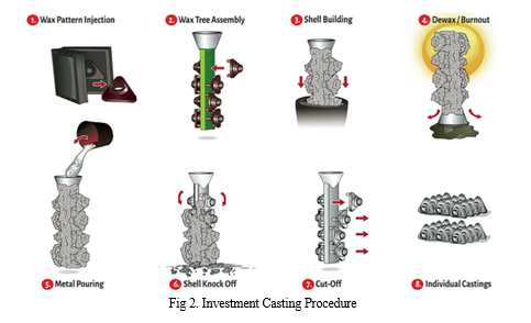
The process of investment casting, also known as lost wax casting, is an archaic technique for shaping metal. The process of investment casting involves the application of refractory ceramic slurry onto a wax pattern, followed by stuccoing and sequential drying to create a series of ceramic moulds, Figure. 2. Subsequently, the wax is melted away, leaving behind a cavity. At this stage, a molten alloy can be introduced into the cavity, where it solidifies and takes the shape of the cast component. Once the solidification is complete, it is separated from the casting through mechanical or chemical means. Finally, the casting undergoes finishing procedures to achieve the final form of the component [2].
The accuracy of the investment casting component is contingent upon the precision of the wax patterns employed. Due to the fact that wax patterns are produced via injection molding using a die, the creation of molds is a costly endeavor. Therefore, 3D-printed patterns may substitute wax patterns, which eliminates the complexity of mold-making and reduces casting turnaround time. Consequently, patterns manufactured using additive manufacturing have the potential to supplant traditional molded wax patterns [3, 4].

The need for manufacturing systems and companies to be adaptable to societal, market, and supply chain changes is increasing rapidly. Industry 4.0 solutions can foster manufacturing flexibility, shorter innovation/development cycles, faster decision making, and resource efficiency. However, there is a lack of a methodology to evaluate the potential impact of Industry 4.0 on manufacturing flexibility and profitability [5].
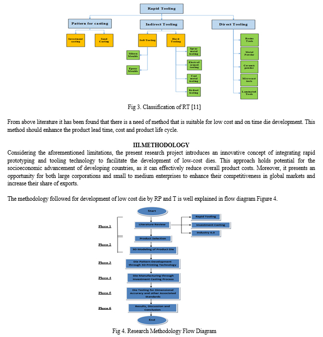
The concept of Rapid Tooling (RT) is concerned with the prompt fabrication of functional parts intended as tools, such as dies and molds, rather than prototypes or operational components. The creation of these tools is accomplished through a variety of manufacturing techniques, which were previously referred to as Rapid Prototyping processes, including Investment casting, Stereo-lithography (SL), Fused Deposition Modeling (FDM), Selective Laser Sintering/Melting (SLS/SLM), 3D Printing (3DP), and Electron Beam Melting (EBM) [6].
The definition of additive manufacturing (AM) as expounded by STM can be encapsulated as follows: "AM is a process of amalgamating materials to engender objects based on 3D model data, with an emphasis on layer-by-layer construction, diverging from the subtractive manufacturing methodologies. Synonyms for AMencompass additive fabrication, additive processes, additive techniques, additive layer manufacturing, layer manufacturing, and free form fabrication". While AM has been in existence as a method of material manipulation for arguably more than two decades, it has only recently emerged as a consequential commercial manufacturing technology [7].
Certain conventional tool-making approaches, which rely on reproducing models, have been modified, and novel techniques that enable the direct fabrication of tools via RP have been created [8].
Rapid tooling is a set of techniques used to quickly produce molds or tools that are used for the mass production of parts or products. These techniques are often used in industries such as automotive, aerospace and consumer electronicswhere there is a high demand for quickly producing high-quality parts. There are several different techniques that can be used for rapid tooling, including [9].
Indirect RT methods usually comprises of Metal deposition, Room temperature vulcanization, Epoxy tooling, Ceramic-Tooling, Spin casting, Investment casting, Fusible metal core and sand casting[10,11].
Direct rapid tooling (RT) methods offer the possibility of manufacturing inserts with the capability to withstand a few dozen to tens of thousands of cycles, serving as a suitable alternative to traditional mould-making techniques.
Common methods of direct RT are Injection Molds, laminate tooling, Rapid tool process, sand form, direct EOS tool, Direct metal tooling using 3DP and topographic shape formation [10, 12].


IV. RESULTS AND DISCUSSION
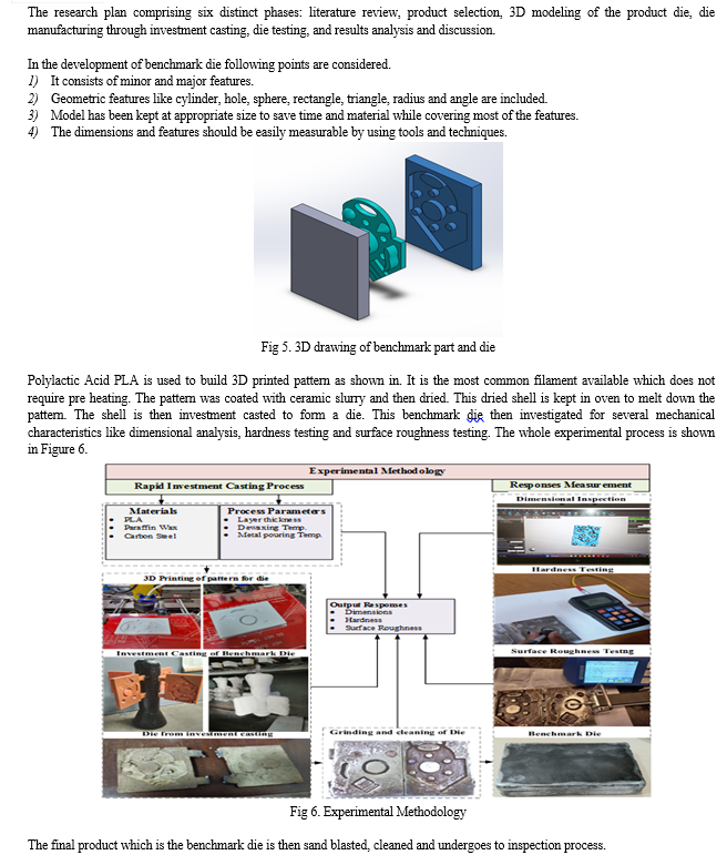
The model including linear and angular sizes, geometric shapes, profiles, and geometric dimensions. Each individual geometric feature, along with its size, orientation, and location, serves a distinct purpose within the context of the assessment. For instance, the inclusion of a flat base serves the purpose of evaluating flatness, as it provides support for all the standing features. Symmetrical faces are strategically integrated to measure relative distance and parallelism, while side walls are specifically designed to quantify angularity between two planes.
In order to assess diametric accuracy, relative distance, position, and pitch circle diameter, six holes were meticulously incorporated into the model. Solid cylinders were skilfully implemented to evaluate roundness, cylindricity, and repeatability. Additionally, the utilization of hollow cylinders serves a similar purpose, with the added objective of testing accuracy, cylindricity, and concentricity.
Furthermore, certain features such as slots positioned above the base, ribs, and thick linear dimensions were introduced to test the machine's capability to generate flat dimensions that exhibit variation. Two free-form surfaces were thoughtfully developed on the flat face, with one aligned horizontally and the other vertically. This was done to thoroughly examine the accuracy of profiles that continuously vary. The placement of a sphere serves as a means to test the accuracy and repeatability of surfaces exhibiting continuously varying slope profiles. On the other hand, the cone surface presents a specific taper angle, allowing for the evaluation of slope profiles. Lastly, theinclusion of a hollow ellipse serves as a benchmark for maintaining a round profile.
The comparison of die for dimensional accuracy was done with the set values and pattern dimensions. Hardness and surface roughness values are compared with the conventionally machined die. For dimensional inspection 3D scanner is used but for the complex geometries vernier caliper and depth gauge is used. For perpendicularity, circularity and parallelism calibrated table and dial gauge is used. For angularity bevel protector is used.

From results it is observed that the least difference was on horizontal profile which is 0.04 and the highest difference was observed in height which is 2.98. And for the accuracy, the values range from between 90.2% for the flatness to 99.8% for the Horizontal profile, whereas the largest percentage deviation is 9.79% for flatness and least percentage deviation is 0.18% for horizontal profile. By using the Equation 3, the calculated percentage of accuracy achieved is 92.43%.
The hardness calculated to be 238HB which is accepted for die. Conventional dies have hardness values ranging between 40-60HRV and dies used in making pattern for investment casting have hardness values between 20-40HRV [13]. The least surface roughness of our casted benchmark die came out to be 0.514 microns (grade N9) and the highest value was indicated to be 6.421 (grade N5) microns which indicate that we can achieveN5 grade by further improving our methods. The standard surface roughness is 3.2 microns [14].
The results of this research work are surprisingly matching as of CNC or conventional machining. By comparing dimensional analysis, geometric features, hardness and surface roughness we can say that this method can be used as a substitute to machining to save time and cost.
V. ACKNOWLEDGMENT
The The experiments of this research work has been performed at Investment casting facility of Heavy Industries, Taxila, Pakistan and the testing and inspection was done at Estenad Industries, Jubail, Saudi Arabia.
Conclusion
This research works introduces a novel method of manufacturing a die through investment casting process. In this work the dimensional features and mechanical properties are investigated and it is concluded that this method holds a potential to overcome the high cost and time in die manufacturing process. It will help in the development of small and medium industries of under developed countries.
References
[1] Singh, J., Investigations and mathematical modeling using dimensionless analysis for hardness of SS-316L implants fabricated for batch production through rapid investment casting. Advances in Materials and Processing Technologies, 2020. 8. [2] Nayak, K. and N. Ramesha, Additive Manufacturing Approach to Investment Casting. 2019. [3] Chhabra, M. and R. Singh, Rapid Casting Solutions: A Review. Rapid Prototyping Journal - RAPID PROTOTYPING J, 2011. 17: p. 328-350. [4] Del Vecchio, C., et al., Support Vector Representation Machine for superalloy investment casting optimization. Applied Mathematical Modelling, 2019. 72: p. 324-336. [5] Höse, K., et al., Manufacturing Flexibility through Industry 4.0 Technological Concepts—Impact and Assessment. Global Journal of Flexible Systems Management, 2023. 24. [6] Pereira, M., M. Williams, and W. Du Preez, Application of laser additive manufacturing to produce dies for aluminium high pressure die-casting. South African Journal of Industrial Engineering, 2012. 23(2): p. 147-158. [7] Frazier, W.E., Metal Additive Manufacturing: A Review. Journal of Materials Engineering and Performance, 2014. 23(6): p. 1917-1928.. [8] Sharma, V. and A. Kumar, Additive Manufacturing in Industry 4.0: Methods, Techniques, Modeling, and Nano Aspects : Book Cover. 2022. [9] Monzón, M., et al., Validation of electrical discharge machining electrodes made with rapid tooling technologies. Journal of Materials Processing Technology, 2008. 196(1): p. 109-114. [10] Pham, D.T. and S.S. Dimov, Rapid prototyping and rapid tooling—the key enablers for rapid manufacturing. Proceedings of the Institution of Mechanical Engineers, Part C: Journal of Mechanical Engineering Science, 2003. 217(1): p. 1-23. [11] Shan, Z., et al., Rapid tooling using plasma spraying and rapid prototyping. Proceedings of the Institution of Mechanical Engineers, Part C: Journal of Mechanical Engineering Science, 2003. 217(1): p. 97-104. [12] Guan, L., Rapid metal tooling based on rapid prototyping. Master\'s dissertation, Tsinghua University, 2000: p. 6. [13] De Santis, R., et al., 3D fibre deposition and stereolithography techniques for the design of multifunctional nanocomposite magnetic scaffolds. Journal of Materials Science: Materials in Medicine, 2015. 26(10): p. 250. [14] Kafle, A., et al., 3D/4D Printing of Polymers: Fused Deposition Modelling (FDM), Selective Laser Sintering (SLS), and Stereolithography (SLA). Polymers, 2021. 13(18): p. 3101.
Copyright
Copyright © 2024 Ahmed Khan, Muhammad Sajid, Ahmad Wasim, Salman Hussain, Mirza Jahanzaib, Hussain Saeed Tunbell, Nikhil Hombegowda. This is an open access article distributed under the Creative Commons Attribution License, which permits unrestricted use, distribution, and reproduction in any medium, provided the original work is properly cited.

Download Paper
Paper Id : IJRASET58208
Publish Date : 2024-01-28
ISSN : 2321-9653
Publisher Name : IJRASET
DOI Link : Click Here
 Submit Paper Online

