Ijraset Journal For Research in Applied Science and Engineering Technology
- Home / Ijraset
- On This Page
- Introduction
- Conclusion
- References
- Copyright
Reliability Improvement of EP-UHR Belt Joint
Authors: Kaushal Kumar Singh, T. Thirumurugan, Himangshu S. Mandal, N. Rajesh Kumar
DOI Link: https://doi.org/10.22214/ijraset.2024.58468
Certificate: View Certificate
Abstract
Introduction
I. BACKGROUND
This UHR based belt conveyor was installed in year 2012. Since commissioning this conveyor belt joint reliability was a concern in joint due to crack in channels or at 2nd step of splicing. Several UHR belts (EP or aramid fabric) with multiple manufacturers were tried but problem was not resolved. In year 2018, Capacity enhancement project of this circuit was taken by plant, wherein the drive pulley diameter was increased from 500 mm to 630 mm, but no improvement was observed in belt joint life.
This belt joint failure was holistically studied, including system analysis wrt transition distance, tension variation, belt construction & rating, validation of counterweight, troughability, temperature effect, minimum pulley diameter calculation, splicing & Jointing process.
Belt joint crack history (during FY12 to FY20) is shown in table-1 below:
Table-1
|
S |
Jointing (New/ Re-joint) date |
Joint life (month) |
Reason of re-joint |
Belt supplier |
Joint making team |
|
1 |
01.04.2012 |
8 |
Belt change |
AA |
A |
|
09.12.2012 |
3 |
Crack in joint area |
C |
||
|
2 |
06.03.2013 |
2 |
Belt change |
BB |
A |
|
05.05.2013 |
2 |
Crack in joint area |
B |
||
|
03.07.2013 (Clip) |
2 |
Crack in joint area |
A |
||
|
3
|
31.10.2013 |
2 |
Belt change |
AA |
D |
|
16.12.2013 |
6 |
Air pocket in joint |
C |
||
|
25.06.2014 |
4 |
Crack in joint area |
A |
||
|
14.7.2014 |
1 |
Crack in joint |
B |
||
|
4 |
08-10-2014 |
5 |
Belt change due to burning |
CC |
C |
|
24-03-2015 |
7 |
Joint open |
B |
||
|
05.05.2015 |
2 |
Crack in joint-Repair |
B |
||
|
5
|
07-10-2015 |
5 |
Worn out belt |
B |
|
|
17-03-2016 |
3 |
Side edge damaged |
B |
||
|
6 |
15-06-2016 |
5 |
Joint opened from top |
History not available |
B |
|
21.09.2016 |
3 |
Belt and joint burnt |
B |
||
|
7 |
23-11-2016 |
8 |
Belt tear |
B |
|
|
8
|
06-07-2017 |
7 |
Crack in joint |
B |
|
|
9
|
01-02-2018 |
7 |
Aramid belt installed |
DD |
B |
|
27.03.2018 |
1 |
Aramid joint overlap opened |
B |
||
|
02.12.2018 |
1 |
Crack in joint area |
C |
||
|
07-02-2019 |
2 |
Aramid joint failed |
C |
||
|
28.04.2019 |
2 |
Aramid belt joint snapped |
B |
||
|
10
|
29-04-2019 |
3 |
EP fabric belt installed |
DD |
B |
|
02-07-2019 |
3 |
Crack in re-joint |
A |
||
|
04-10-2019 |
0.5 |
Joint clipping due to crack in joint |
|
||
|
15-10-2019 |
0.5 |
Joint clipping due to crack in joint |
|
||
|
29-10-2019 |
|
Belt Snapped from joint |
|
||
|
11 |
05-11-2019 |
Running |
Belt change with hot joint |
DD |
|
|
23-12-2019 |
Running |
Air pocket formed & repaired |
Based on table-1, the belt joint life is observed max-09 months & min-02 months (outlier is one month, it was a special case where wrong selection of splicing kit of Aramid belt, this was accepted by splicing kit supplier).
During belt jointing on dated 29.04.2019, the jointing team had not used long flat roller subsequently air pocket was formed in the joint and these air pockets were further moved out at top channel area in the form of crack, whereas ply-ply butt joints edge, but generally this type of air pocket and joint overlap separation starting from top channel appears within 1 to 2 weeks of jointing. After 2 months, due to crack in joint, on 02.07.2019 this belt was re-jointed by hot vulcanizing with supplier splicing kit.
The belt hardness was checked after re-jointing & found 53-55 A shore (jointing zone) at channel area & 65-69 A shore in mother belt. After 3 months, this joint has again developed crack and it was fastened by mechanical clip on 04.10.2019. Then, On 15.10.2019, belt joint was again repaired by refastening of mechanical clips.
This repaired joint was snapped on dated 29.10.2019. The snapped joint piece has taken and sent to Lab for adhesion, tensile and abrasion tests. But due to several mechanical fasteners in joint zone, it is very difficult to get the observation which led to this situation however the analysis was based on the residual condition of joint.
II. OBSERVATION
Belt was snapped from 2nd step of splice joint and multiple patch plates (coverage area was 1st step, 2nd step and 3rd step of joint) were found which was fixed by mechanical fasteners because the top channel was opened in joint.
Snapped joint was checked after removal of mechanical fasteners & patched covers. The joint crack appeared at channel in cover rubber & tear in 2nd step of joint. The failed belt joint step length was found 200 mm.
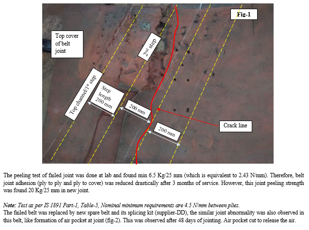

Belt conveyor alarm history was checked and found that alarm on object BC_MA01 has been requested several times & these had been acknowledged by operator.
Comment by lab: Tested and valid splicing kit was used for joint making. Test joint piece was tested at lab and got result 15 kg/25mm against minimum requirement of 11.5 kg/25mm. Earlier in Oct’2018 same type splicing kit was used in same type of belt and found result 15 kg/25mm. Same lot splicing kits were also used at jointing team separately and got result 20 kg/25mm. No issue with splicing kit and adhesion.
Comparison of UHR belt performance with other loactions: Similar belt cracking problem happens, but the surface cracks appear in entire belt due to heat instead of joint.
Plant Maintenance Status: Compliance is checked and found more than 95%.
III. DETAIL ANALYSIS
A. Improper belt Jointing
- A.1: Splicing kit: As per jointing team, Test joint was made with belt and splicing kit of supplier-DD as per SOP, further the joint peeling strength was checked & found 14 Kg/25 mm. The previous belts joints were also failed but their peeling strength were more than 18 Kg/25 mm. Hence joints peeling strength were found OK.
- A.2: Jointing SOP & joint step length was checked and found as per OEM recommended.
- A.4: Poor workmanship during jointing: Probable issues with workmanship are tackled as overlapping of insulation compound, non-standard tools and tackles, inadequate skill for jointing of workmen/untrained jointer (workmen), violation of belt jointing SOP, jointing time might not be maintained as per SOP, moisture ingression in joint during jointing and improper vulcanizing pressure or curing temperatures during the joining process. These conditions might be the causes but these workmen (team) are jointing UHR belts (similar grade) in other loaction and nowhere this type of joint failure has been observed.
B. Material High Temperature
- During Belt Running
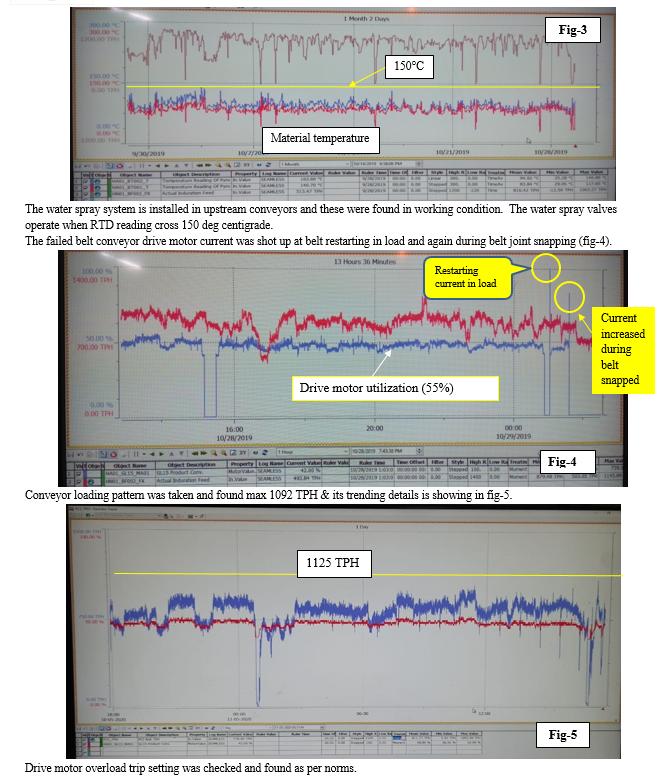
On dated 17.06.2019, Thermography of loaded material on belt was done by central monitoring team at site in running condition & found maximum average temperature 230°C, whereas 285°C by area maintenance, which is more than maximum bearing continuous temperature (180°C) capacity of UHR grade belt. During dated 29.09.2019 to 29.10.2019 (belt snapped date), as per online material temperature trend (fig-10), the loaded material temperature was found below the 150°C. As per central monitoring team report, the thermal crack in belt normally generates at edge of 2nd step in joint zone, where one ply present in top. Belt should not be stopped with hot material because this affects the joint. Hence material temperature variations were observed based on above two measurements. The edge re-straining idlers (2 nos.) were installed just before the hood of discharge pulleys to maintain the required trough shape of belt. This failed belt was not found permanent deformation in shape due to heat because of lesser service of life. Hence belt shape changes due to heat sensing by hot material.
2. Water Spray System
The water spray systems at up stream conveyors are spraying water for reducing the material temperature. Due to quenching effect, cover rubber hardness got increased & supported in creep strain in butt joint at channel (1st step) or 2nd step of belt jointing area. Further water vapour (steam) ingression through air pocket pin holes/cut and delaminate the splice of joint. Subsequently crack was generated in path of vapour flow.
3. During belt Stopped in Load
The failed belt top cover was found free from localize heat damage (hot patch, heat sensed impression etc.) by visually due to heat insertion by carrying hot material because of very short period of belt service life.
C. Inadequate Belt Selection
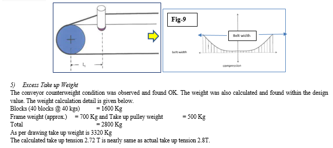
- Low Heat Resistance Cover Rubber: As based on the belt failure history as per table-1, the failed belts were supplied by the various manufacturers (Indian & Overseas) but the all belts failure mode is almost similar (only joint failure). As per fig-3, the material temperature trend was found below 150°C but as per the central monitoring team thermography report, the material temperature was found max. 230°C however, this belt could have taken care of max. belt surface temperature 220°C as per the belt datasheet. Hence the selection of cover rubber grade (heat resistance) is not inadequate.
- High Belt Modulus: As per supplier-DD belt data sheet, the failed belt was belt modulus 6300 KN/m (10 times of EP fabric belt rating). However further supplied belts have belt modulus 6490 KN/m as per supplier-DD. which is higher and might be affected the belt troughability. Hence belt rating should be selected as per CEMA standard.
- Belt Selection Error: High tensile strength
- Drive motor max power consumption @ 55% = 41.60 kW (as per fig-4 & 5)
Maximum running TPH=1500 x 5.5/8 = 1031.25 ~1032 TPH
As per belt stat software, drive motor max power consumption is also 41 kW. Shown in table -2.


IV. RECOMMENDATION
A. Corrective
- Flat roller to be used in joint making process during insulation laying and overlapping.
- Fabric breaker ply to be used over butt ply joint of top channel to prevent exposure of channel ply.
- Existing and all old material code of conveyor belt to be blocked
B. Preventive
- Change in belt Specification: Modification in new belt Mareial Code
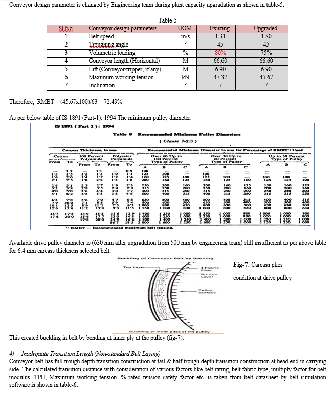
a. Belt carcass thickness to be reduced from 6.4 mm to thickness lower than 5.8 mm to accommodate existing drive pulley diameter (630 mm) of EP 630/4 rating belt as per standard IS 1891 (Part-1):1994 & ISO 3684
b. Belt rating (tensile strength) 500/4 to be used instead of 630/4 to address the high belt modulus and minimize deferential tension between inner & outer surfaces of the carcass.
c. Proposed belt to be selected with standard cover thickness ratio (≤3) to maintain the belt neutral axis.
2. Change in System
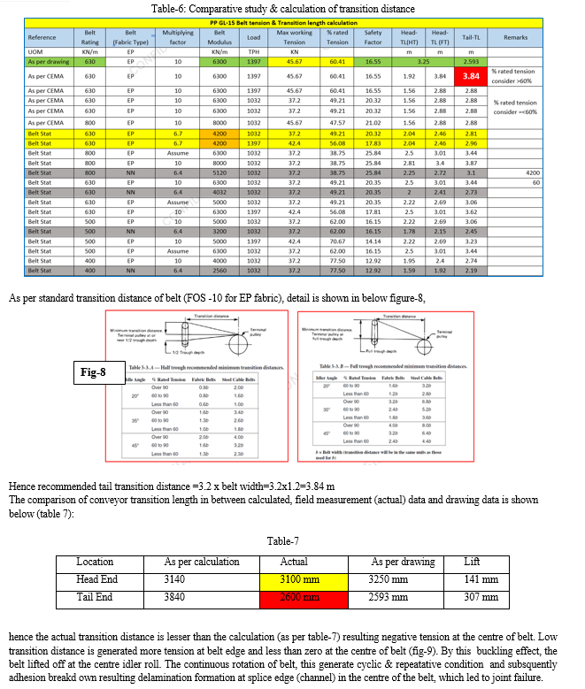
a. Transition distance to be increased from 2600 mm to 3840 mm at tail end (carrying side)
b. Water Spray system to be modified to automized water spray system for reducing/eliminating the quenching effect on belt (material temperature to be controlled and average temperature must not be more than 180°).
c. Receiving chutes to be modified to minimize the material dead (pile) load on the belt during downstream conveyors tripped/stopped in load condition (when only one up stream screen in service)
C. Suggestive
a. The proposed belt maybe selected PP fabric instead of EP fabric to reduce the of belt modulus and subsequently increase the troughability.
b. Belt joint step length to be increased from 200 mm to 300 mm for improvement of joint efficiency
c. Pyrometers of up stream conveyors to be rechecked and re-calibrated.
d. UHR belt should not be stopped with hot material.
V. NOMENCLATURE
- UHR – Ultra heat resistance
- AA/BB/CC/DD – Supplier name
- A/B/C/D – Belt jointing team
- SOP – Standard operative procedure
- DCS – Distributed control system
- RTD – Resistance temperature detector
- TPH – Ton per hour
- OEM – Original equipment manufacturer
- EP – Polyester
- RMBT - Recommended maximum belt tension
- FOS – Factor of safety
Conclusion
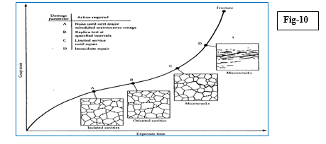
The calculated pulley diameter is less than the standard value (as per standard IS 1891(Part-1):1994 & ISO 3684) therefore carcass top ply had sensed higher tension & bottom ply higher compression. Also the higher belt rating 630/4 has higher belt modulus (6490 KN/m) which created higher differential tension in between top ply to bottom ply of carcass & subsequently generates Isolated cavities---?Oriented cavities---?Micro cracks---?Macro cracks---?Surface crack at channel or at 2nd step of splice in butt joint zone(fig. 10). Water spray system in upstream conveyors generates steam (material temperature>100°C, sometimes more than 200°C, steam contact with top cover rubber resulting hot water or steam seeps into cracks and able to penetrate through the belt cover down to the actual carcass of the belt. In multi-ply belts, the fibre of the weft strands of the plies expand as they absorb the moisture or steam. Which in turn causes sections of the carcass to contract(shorten)as the weft strands pull of the wrap strands of the ply this phenomenon when repeatedly happens, the ply breaks. After that, this moisture vapour (steam) of pellet fines penetrated and reached up to the joint splice layers. Low tail transition distance (2600 mm instead of 3840 mm at carrying side) is generated more tension at belt edge and lesser at the centre of belt. Existing belt 630/4 (high tensile rating as per maximum belt tension 47.5 KN at drive pulley as per design data sheet) has high belt modulus resulting low troughability in belt and demands high transition distance. Excessive stress cycle in the belt because of short conveyor length (~150 m) at butt joint of channel/2nd step resulting joint fatigue crack at splice edge (channel)/splices in the centre of the belt and finally led to break/separation/snapping of joint in shear mode.
References
[1] Failure Analysis & Plant Metallurgical Investigation, Tata Steel, Scientific Services, File No. SS/MEL/REG/074 [2] Himangshu Mandal, Investigation Report, Tata Steel, India, IR-TSL/OSSTG/JSR/TR/0135/2020 FN-MEG/Form/32, CRN- 300004899982 [3] IS 1891 (Part-1): 1994, , Nominal minimum requirements of adhesion resistance between plies and ply to cover. drive pulley diameter [4] ISO 3684- drive pulley diameter [5] Ranjan Goswami, Rubber Technology Group, FN- EHSMSM/446/4013/SOPN- MED (M)/RTG/SOP/006 [6] Dave Pitche, Fenner Conveyor Belting (SA) (Pty) Ltd. Determination of Minimum Pulley Diameters for Belt Conveyors.
Copyright
Copyright © 2024 Kaushal Kumar Singh, T. Thirumurugan, Himangshu S. Mandal, N. Rajesh Kumar. This is an open access article distributed under the Creative Commons Attribution License, which permits unrestricted use, distribution, and reproduction in any medium, provided the original work is properly cited.

Download Paper
Paper Id : IJRASET58468
Publish Date : 2024-02-16
ISSN : 2321-9653
Publisher Name : IJRASET
DOI Link : Click Here
 Submit Paper Online

