

Ijraset Journal For Research in Applied Science and Engineering Technology
Comparative Study on the Seismic Analysis and Wind Analysis of Multistorey Building with Shear Wall and Diagrid
Authors: Anita Popatrao Borde, Prof. R. S. Gunjal
DOI Link: https://doi.org/10.22214/ijraset.2025.66857
Certificate: View Certificate
Abstract
The present study investigates the behaviour of G+50 storey octagonal shaped building provided with shear wall at different locations and diagrid, by inter-combining all these parameters of shear wall and diagrid; total six model of G+50 storey building are prepared. The seismic and wind analysis of G+50 storey building is carried out by using structural analysis and design computer program STAAD Pro. The dynamic analysis (Response Spectrum Method) of G+50 storey octagonal shaped building with shear wall at a different locations and diagrid is carried out by using structural analysis and design computer program STAAD Pro. All the models are developed for seismic zone III as per IS 1893: 2002 (part I) and for wind analysis zone II is considered i.e. Aurangabad city having a basic wind speed of 39 m/s as per IS 875: 1987 (part-III). All the models are analyzed by considering seismic forces and wind forces. The main aim of this research work is to find out the suitable location of the shear wall and the model under seismic forces and wind forces which give optimum results. The behaviour of each model with respect to others is checked for Base Shear (VB), Axial Force (FX), Twisting Moment (MX), Bending Moment (My), Bending Moment (MZ), and Lateral Displacement (?) at each and every storey are carried out for seismic forces and wind forces separately. Finally, the behaviour of each model with respect to others for seismic force and wind force is described with the help of graph.
Introduction
I. INTRODUCTION
The rapid growth of urban population, scarcity and high cost of available land, the taller structures are preferable now days. As the height of structure increases; consideration of lateral load is very important. Hence the lateral load resisting system becomes more important than the structural system which resists the gravitational loads. The lateral load resisting systems that are widely used are rigid frame, shear wall, diagrid structural system, wall frame, braced tube system, outrigger system and tubular system. Recently shear wall systems and diagrid structural system are the most commonly used lateral load resisting systems. Shear walls have very high in plane stiffness and strength, which can be used to simultaneously resist large horizontal loads and support gravity loads, making them quite advantageous in many structural engineering applications. Diagrid structural system is adopted in tall buildings due to its structural efficiency and flexibility in architectural planning. Diagrid – diagonal grid structural systems are widely used for tall buildings due to its structural efficiency and aesthetic potential provided by the unique geometric configuration of the system. Hence the diagrid, for structural effectiveness and aesthetics has generated renewed interest from architectural and structural designers of tall buildings.
A. Shear Wall
Shear wall is the vertical element of the horizontal force resisting system. Shear wall is constructed to counter the effects of lateral load acting on a structure. In residential construction, shear walls are straight external walls that typically form a box which provides all of the lateral support for the building. When shear walls are designed and constructed properly, they will have the strength and stiffness to resist the horizontal forces.
The shear wall is classified as below:
Simple rectangular types and Flanged walls (Barbell type)
- Coupled shear wall
- Rigid frame shear wall
- Framed walls with in filled frames
- Column supported shear walls
- Core type shear walls
B. Diagrid
The term diagrid is a combination of words “diagonal” and “grid”. Diagrid is particular form of space truss, which does not have any conventional column on the exterior periphery of structure. It is formed by intersecting the diagonal columns and horizontal beams and is made up of series of triangulated truss system. It is a design for constructing large buildings with steel that creates triangular structures with diagonal support beams. It may be straight or curved, and horizontal rings which together make up a structural system for a skyscraper.
The materials used in the construction of diagrid are steel, concrete and wood. Following factors affect the selection of material-
- Availability of material
- Erection time
- Flexibility
- Durability
- Unit weight of the material
- Labour cost
- Lead time
- Fire resistance
Types of Diagrid Structural System:
a) Steel Diagrid Structural System
The most common and popular material used in the construction of diagrid is steel. The sections commonly used are rectangular HSS, rounded HSS and wide flanges. The weight and size of the sections are made so as to resist the high bending loads. They can be quickly erected and the cost of labour for the installation is low.

Figure 1: Steel Diagrid Structural Systems
b) Concrete Diagrid Structural System
Concrete is also commonly used diagrid material. The concrete diagrid are used in both type, precast and cast in-situ. As the precast concrete sections are flexible, it allows them to fit perfectly in the structure geometry. It also protects from the fire damages. But the precast concrete constitutes more to the dead load of structure.

Figure 2: Concrete Diagrid Structural System
c) Timber Diagrid Structural System
Timber is rarely used for diagrid system. The advantage of this material is that the sections of timber are easily available in any shape and size. The installation cost is low. The major disadvantages are that timber has lesser material strength. Durability and weathering of timber are the major issue that makes for the disadvantages of timber as a diagrid construction material.

Figure 3: Timber Diagrid Structural System
II. LITERATURE REVIEW
Lee et al. (2016) performed finite element analysis of optimized brace angle for the diagrid structural system and also studied the cyclic performance of a diagrid node with an H-section brace with an emphasis on the welding methods, overlapped length, and diagrid angle. Details that improve productivity were proposed and the structural performance was assessed through experimental and analytical investigation.
Menon et al. (2016) designed and analysed 30 storey RC building with steel diagrid and studied performance assessment of high-rise building. A regular plan of 36m X 36m size is considered. Four different storey modules are prepared to decide the angle of diagrid such as 2 storey module, 3 storey module, 4 storey module and 6 storey module. Modelling and analysis of structural members have done using ETABS software. All structural members are designed as per IS 456:2000 and IS 800:2007 considering all load combinations. They have studied seismic performance by analytical methods such as equivalent static analysis, nonlinear static pushover analysis and linear time history analysis using ETABS analysis package and also found out optimum angle for 30 storey RC building with steel diagrid. It has been concluded that optimum angle for 30 storeys RC building with steel diagrid is 67.4 degree. Equivalent static analysis results showed that less top storey displacement and storey drift for 3 storey module and also time period is less for 4 storey module (67.4)?. The equivalent static analysis did not give any idea about the ductility of the structure, therefore nonlinear static pushover analysis results showed high stiffness and moderate ductility for 4 storey module (67.4)?. Linear time history results showed less overturning moment, storey shear, column force for 4 storey module (67.4)?.
Venkolath et al. (2016) performed analysis of 24 storey circular building to find the optimal diagrid angle to minimise the lateral drift and displacement in a high-rise building. The circular plan of 30.7 m diameter is considered with five different types of angles of diagrid that is 36.8°, 56.3°, 66°, 77.5° and 83.6°. The results were tabulated by performing finite element analysis using ETABS software. The comparison of analysis of results in terms of lateral displacement, storey drift, storey shear and time period. It has been concluded that diagrid angle in the region of 65° to 75° provides more stiffness to the diagrid structural system which reflects the less top storey displacement. The storey drift, storey shear, time period, effect of lateral force to stories are very much lesser in the region of diagrid angle. The optimum angle observed in the region of 65° to 75°.
Abhinav et al. (2016) performed seismic analysis of multi-storey building with the shear wall using STAAD Pro. An RCC building of 11 floors placed exposed to earthquake loading in zone V is considered and earthquake load has calculated by the seismic coefficient method using IS 1893 (Part I): 2002. The three models of 11 floor building have been made with the shear wall at corner, shear wall along periphery and shear wall at middle of the building. The comparative study of deflection of building with and without shear wall is carried out in X and Z directions. The lateral deflection for building with shear wall along periphery is reduced in comparison to other models. Hence, it has been concluded that the building with a shear wall along periphery is much more efficient than all other models with a shear wall.
Nandeesh et al. (2016) performed comparative study of 52 storey hyperbolic circular steel diagrid structural system rehabilitated at central core with shear wall and steel braced frames. This work basically comprised of two models with shifting floor zone and centre divider framework. The external fringe comprises of diagrid funnel segment for both models. These models are examined for two distinctive seismic zones (zone II and zone III). All the models and its components are investigated utilising ETABs programming according to Indian codes. The present work showed the outcomes parameter regarding story drift, story displacement, time period, story shear. It has been concluded that the shear wall shows the better performance under earthquake loading. Shear wall had less top storey displacement, storey drift than steel bracing systems in both seismic zones. The steel bracing system gave better performance against storey shear for both seismic zones than shear walls system. The shear wall systems act as a monolithic structure and gives the effective performance against all aspects in terms of maximum storey displacement, storey drift and time period.
Azad et al. (2016) [8] performed a comparative study of seismic analysis of multi-story buildings with shear walls and bracing systems. This paper contained a numerical approach to show dissimilarity between the shear wall system and steel bracing system. The new approach of this research was strengthening lateral force resisting system by using steel bracing. A gradual process has been done step by step to show comprehensible contrasts between the systems. For implicit results, East Malaysia has considered as the corresponding region. The overall analysis has been carried out using the ETABS9.7 software. Six models have prepared for the comparative study. The first model was having a shear wall at middle portion, second model was having shear wall at side portion, third model was having bracing at centre, fourth model was having bracing at side, fifth model was having floor bracing at middle and sixth model was having floor bracing at side. It has been concluded from the results that model one was the safest among the six models.
Tripathi et al. (2016) studied the diagrid structural system for framed multi-storey building and also stiffness based design methodology for determining preliminary sizes of R.C.C diagrid structures for tall buildings. A 36m X 36m size regular plan is considered. Modelling, design and analysis of structural members is done by using ETABS 2015 software. Structural members are designed as per IS 456:2000, load combinations of seismic forces as per IS 1893(part I): 2000 and dynamic along wind and across wind are considered for analysis as per IS 875: 1987 (part 3). Dynamic Analysis of 24, 36 and 48 story building with perimeter diagrid with different story module is carried out by Response spectrum method. There are 15 models are prepared with five different types of angles of diagrid i.e. 50.2°, 67.4°, 74.5°, 78.2° and 82.1° for 2 storey, 4 storey, 6 storey, 8 storey, 12 storey diagrid module for 24-storey, 36-storey, 48-storey building. The results of analysis are compared in terms of top storey displacement, storey drift, storey shear, time period, angle of diagrid, spectra acceleration coefficients, base reactions for seismic and wind forces within same storey height for different storey modules and for different storey heights. The present study concluded that for all 15 models storey displacement and storey drifts are within permissible limit. The storey drift, storey displacement, storey shear etc. are less in the region of 65° to 75° diagrid angle. Therefore optimum angle of diagrid is observed in the region of 65° to 75°.
III. METHODOLOGY
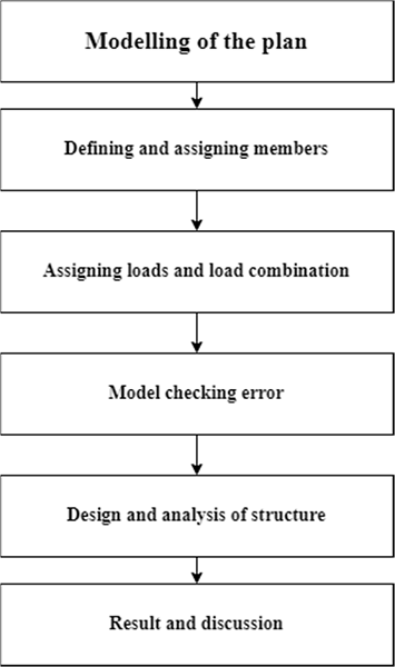
Figure 4: Flow of the proposed model
A. Modeling in STAAD.pro
1) Input Generation
The GUI (or user) communicates with the STAAD analysis engine through the STD input file. That input file is a text file consisting of a series of commands which are executed and /or design. The STAAD input file can be created through a text editor or the GUI Modeling facility. In general, any text editor may be utilized to edit/create the STD input file. The GUI Modeling facility creates the input file through an interactive menu-driven graphics oriented procedure as shown in figure 4.1.
2) Types of Structures
A structure can be defined as an assemblage of elements. STAAD is capable of analyzing and designing structures consisting of frame, plate/shell and solid elements. Almost any type of structure can be analyzed by STAAD.
A SPACE structure, which is a three dimensional framed structure with loads applied in any plane, is the most general. Here we have used a space structure for the analysis and design of G+50 storey building.
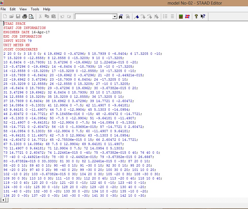
Figure 5: STAAD.pro Editor Input File
A PLANE structure is a type of structure which is bound by a global X-Y coordinate system with loads in the same plane.
A TRUSS structure consists of truss members which can have only axial member forces and no bending in the members.
A FLOOR is 2D or 3D structure having no horizontal (global X or Z) movement of the structure, the floor framing (in global X-Z plane) of a building is an ideal example of this type of structure.
3) Generation of the structure
The structure may be generated from the input file or mentioning the co-ordinates in the GUI. The figure 4.2 below shows the GUI generation model through node element in which columns and beams are model as beam element whereas tank container are model as four node iso-parametric plate element.
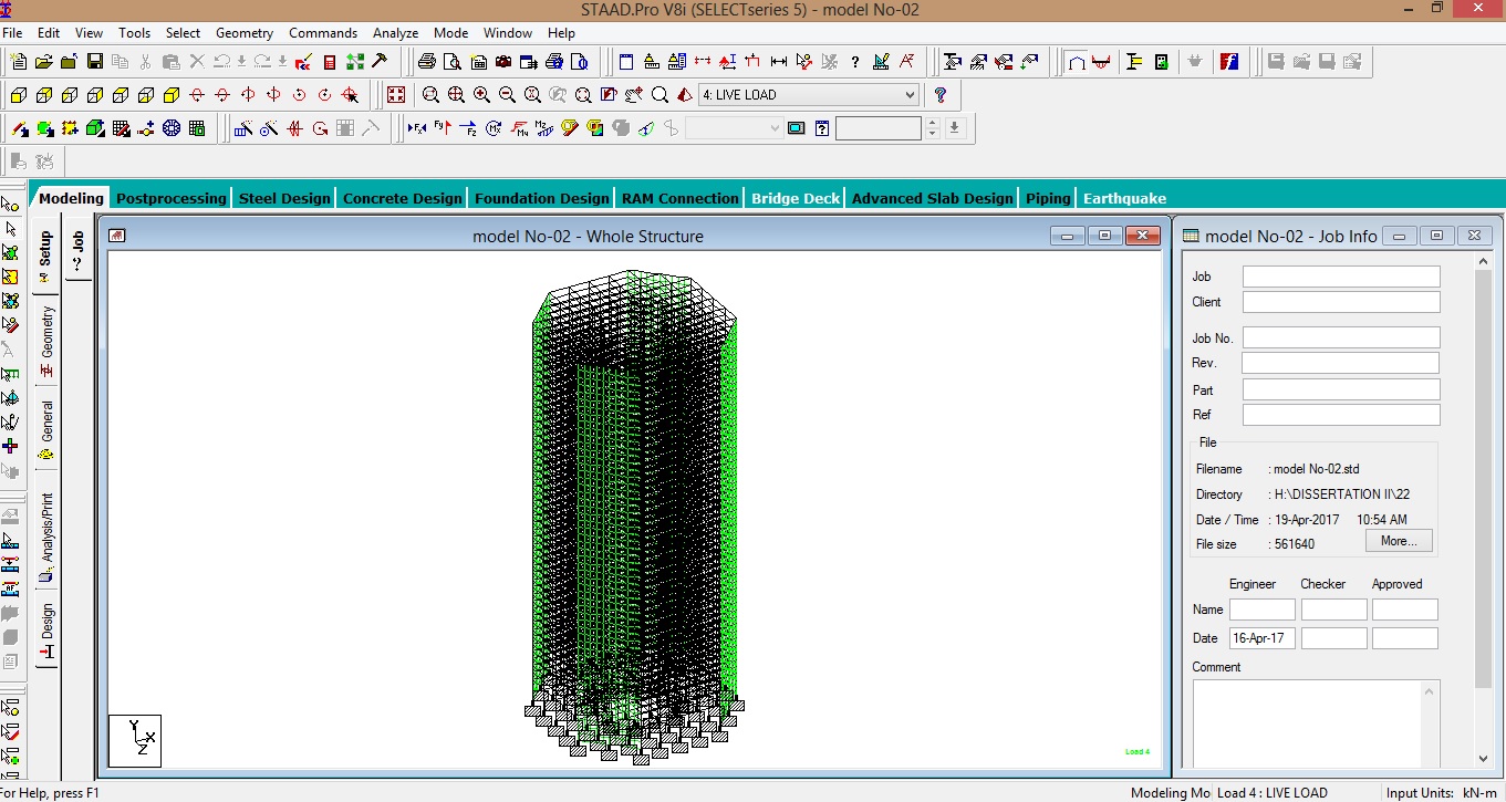
Figure 6: GUI generation in STAAD.Pro
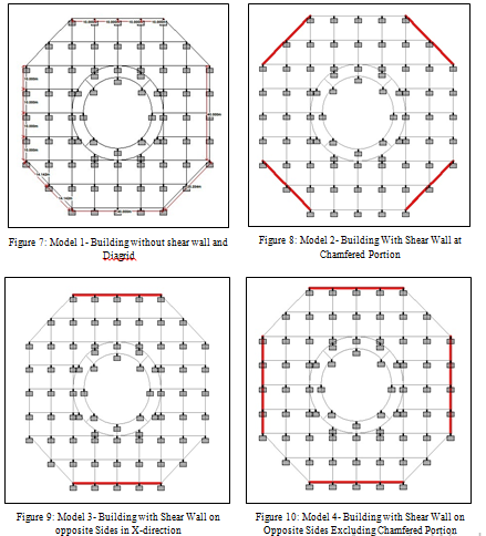
4) Modeling of G+50 storey Building using STAAD.Pro
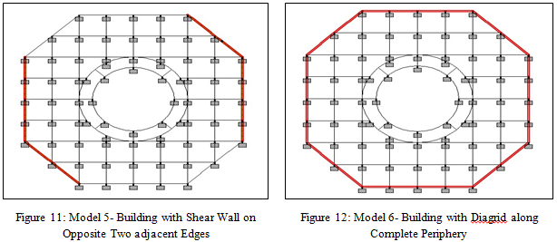
In this work I have considered a reinforced concrete G+50 storey building provided with shear wall at different locations and building with diagrid as shown in figure 4.11 to figure 4.16 respectively. The modeling of G+50 storey building is carried out by considering, building without shear wall, with shear wall and with diagrid (X bracing). The analysis of G+50 storey building under different parameters is carried out by using a finite element based software STAAD.Pro. The beams and columns in the frame type structure are modeled as beam elements with six DOF per node. The shear walls provided at different location are modeled by using four node plate elements.
IV. RESULT AND DISCUSSION
A. Graphs and Observations
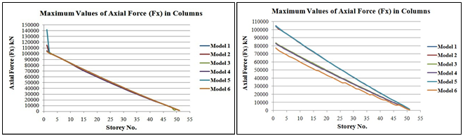
The axial force (FX) considering seismic forces and wind forces at every floor is found out in kN and the graph is plotted for axial force verses storey as shown in Fig-13 a,b respectively. From this both graphs it is clear that the maximum values of axial shear force for each model is at lower stories and is decreasing with increase in storey.
a) b)
Figure 13: Maximum Values of Axial Force (FX) in Columns Considering a) Seismic Forces b) Wind Forces
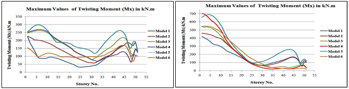
The twisting moment (MX) considering seismic forces and wind forces are found out in kN-m, graphs are plotted for maximum twisting moment verses storey no. as shown in Fig-14 a,b respectively. It is observed that the maximum twisting moments at each story for various model is nonlinear and varying (increasing or decreasing rapidly).
- b)
Figure 14: Maximum values of Twisting Moment (MX) in beams Considering a) Seismic Forces b) Wind Forces
Maximum values of bending moments (My) in kN-m considering seismic forces and wind forces are found out and plotted against Storey No., as shown in Fig-15 a, b respectively. It is observed that for model-6 there is variation in values of bending moment after every 5 storey as the diagrid are extend over 5 storeys. Whereas in other models considering only shear walls maximum values of bending moment is higher at lowest stories and is lowest at higher stories.

a) b)
Figure 15: Maximum Values of Bending Moment (My) in Columns Considering a) Seismic Forces b) Wind Forces
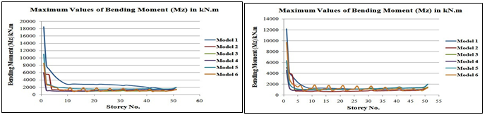
The maximum values of bending moments in Z-direction considering seismic forces and wind forces are found out for each storey and plotted against storey no. as shown in fig 16 a, b respectively. From the graph it is observed that the model-1 shows maximum values of bending moment in both the cases. In the graph for the Model no’s 1, 2, 3, 4 and 5 are decreasing rapidly up to 10 storey and are nearly constant up to 30 storey, then it again decreases slowly and lowest at 50th storey. The graph for models 1, 2, 3, 4 and 5 decreases rapidly up to 5th storey and then it is constant up to 50 storeys. For model-6 there is a variation in the values of bending moment approximately after every 5 stories
a) b)
Figure 16: Maximum Values of Bending Moment (MZ) in Beams Considering a) Seismic Forces b) Wind Forces
The maximum values of the base shear (kN) considering seismic forces and wind forces are found and plotted against storey no. as shown in Fig-17 a, b. The maximum value of base shear is obtained for Model-4.
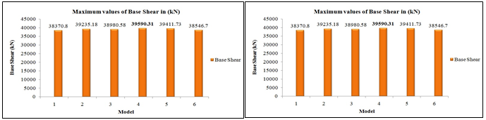
- b)
Figure 17: Maximum Values of Base Shear (VB) Considering a) Seismic Forces b) Wind Forces
The maximum values of lateral displacement (δ) in mm considering seismic forces and wind forces are found and plotted against storey no. as shown in the Fig-18. The lateral displacement is maximum for the Model-3 and Model-1 i.e. models with shear wall at opposite sides in X-direction and models without shear wall and diagrid. The lateral displacement is minimum for lower stories and it increases with increase in no. of stories.

a) b)
Figure 18: Maximum Lateral Displacement Considering a) Seismic Forces b) Wind Forces
Conclusion
From the above results and discussion it is concluded that, 1) The maximum axial force considering seismic forces observed in model-5 and minimum in model-6. The percentage reduction in axial force is from 26 % at ground storey to 5% at top storey. 2) There is 67% reduction in maximum twisting moment in model-6 at 5th storey due to provision of diagrid along complete periphery compared with model-5 and 85% reduction in twisting moment at 50th storey for model-6 due to provision of diagrid along complete periphery compared with model-5. 3) The lateral displacement observed in model-1, 2, and 3 is beyond permissible limit as 0.004 H as per IS1893 (Part I):2002. Lateral displacement is reduced by providing shear wall in opposite faces excluding chamfered portion i.e. Model-4 and it is within permissible limit for both seismic and wind analysis. 4) Building with diagrid along entire periphery i.e. Model-6 gives the optimum values of axial force, twisting moment, bending moment, base shear by considering the seismic forces as compared to other models. 5) Building with shear wall at opposite sides excluding chamfered portion i.e. Model-4 gives optimum values of axial force, bending moment, base shear and lateral displacement considering the wind forces compared to other models. 6) The models of buildings considering seismic forces gives more values of Forces, Moments and Lateral displacements than models considering wind forces.
References
[1] Kirtan. T and N. Jayaramappa, “Comparative Study of Multi-Storey RC Frame with Shear Wall and Hexagrid System” Paripex- Indian Journal of Research, Volume: 06, Issue: 01, pp. 814-817, ISSN 2250-1991, January 2017. [2] Arpan banerji and Vijay Kumar Shrivastava, “Analysis of G+4 Multi-storeyed Building for Various Locations of Shear Wall Considering Effect of Torsion using Response Spectrum Method” International Journal of Computational Engineering Research (IJCER), Volume: 07, Issue: 01, pp. 21-27, ISSN (e): 2250 – 3005, January 2017. [3] Yongjae Lee, Jintak Oh, Hussam Hassan Abdu and Young K. Ju, “Finite Element Analysis of Optimized Brace Angle for the Diagrid Structural System” International Journal of Steel Structures, Volume: 16, Issue: 04, pp. 1355-1363, ISSN:1598-2351, December 2016. [4] Hrdya Menon and Paul Jose, “Performance Assesment of High-Rise Building using Diagrid” International Journal for Innovative Research in Science & Technology (IJIRST), Volume: 3, Issue: 04, pp 74-77, September 2016. [5] Jayesh Venkolath and Rahul Krishnan K., “Optimal Diagrid Angle of High-Rise Buildings Subjected to Lateral Loads” International Research Journal of Engineering and Technology (IRJET), Volume: 03 Issue: 09, pp. 841-846, e-ISSN: 2395 -0056 p-ISSN: 2395-0072, September 2016. [6] V. Abhinav, Dr. S. Sreenatha Reddy, M. Vasudeva Naidu and Prof. S. Madan Mohan, “Seismic Analysis of Multi Story RC Building with Shear Wall Using STAAD.Pro” International Journal of Innovative Technology and Research (IJITR), Volume: 4, Issue: 5, pp. 3776-3779, ISSN 2320 –5547, August 2016. [7] Nandeesh K. C. and Geetha K., “Comparative Study of Hyperbolic Circular Diagrid Steel Structure Rehabilitated at Core With Shear Wall And Steel Braced Frames” International Journal of research in Engineering and technology (IJRET), Volume: 05, Issue: 07, pp.317-323, e-ISSN: 2319-1163, p-ISSN: 2321-7308, July 2016. [8] Md. Samdani Azad and Syed Hazni Abd Gani, “Comparative Study of Seismic Analysis of Multi-story Buildings with Shear Walls and Bracing Systems” International Journal of Advanced Structures and Geotechnical Engineering (IJASGE), Volume: 05, Issue: 03, pp. 72-77, ISSN 2319-5347, July 2016.
Copyright
Copyright © 2025 Anita Popatrao Borde, Prof. R. S. Gunjal. This is an open access article distributed under the Creative Commons Attribution License, which permits unrestricted use, distribution, and reproduction in any medium, provided the original work is properly cited.

Download Paper
Paper Id : IJRASET66857
Publish Date : 2025-02-06
ISSN : 2321-9653
Publisher Name : IJRASET
DOI Link : Click Here
 Submit Paper Online