Ijraset Journal For Research in Applied Science and Engineering Technology
- Home / Ijraset
- On This Page
- Abstract
- Introduction
- Conclusion
- References
- Copyright
Seismic Analysis of Irregular Planned RC Frame: Capacity Based Design Criteria
Authors: Dev Dutt Chaubey, Dr. Raghvendra Singh
DOI Link: https://doi.org/10.22214/ijraset.2022.40634
Certificate: View Certificate
Abstract
This study examines the capacity-based design of structure that is increasing commonly in earthquake resistance design. For making any structure earthquake resistant capacity-based design approach is good to hire because it takes less specialization. Low to medium rise buildings are performing well for the seismic actions when designed as per capacity- based criteria. The other method is to install lateral load resisting element such as shear wall, dampers, base isolators etc. These methods of seismic resistance are costly and requires special attention while installation. On the other hand, capacity based designed approach requires no extra element in frame although making existing frame elements to be stronger. In the present work, three type of irregularity is being taken and those are being imposed over RC frame which has designed as per capacity-based design criteria for four different heights of G+3, G+5, G+7, G+10. Those models are analyzed for commercial use and located at seismic zone IV. Linear static, linear dynamic and nonlinear static methods are used to analyze those models with help of CSI ETABS v19 software. Results which are discussed is modal analysis, storey drift, torsional ratio, ductility ratio, performance point and hinge results.
Introduction
I. INTRODUCTION
The structure is predicted to support vertical and horizontal masses throughout operation among fixed safety limits. Applying seismic design of buildings, the frame structure should have several seismic resistance parameters, one in every of that is the seismic resistance parameter of having strong column and weak beams. In previous earthquakes, plastic column hinges were additional vital than beam hinges, leading to overall structural injury and a high risk of death. All structural members transmit their forces through the column and therefore the column shares them with the foundation, therefore if the column fails the total structure will collapse, this can be a weak column strong beam thought. By creating the column additional moment resistant than the beam, the plastic hinges can move towards the beam and stop overall injury. During this case, solely the beam is bent as a symptom of damage to the beam and occupants can have enough time to evacuate from the positioning and therefore the beam failure is restricted to a particular floor. This idea is Strong Column Weak Beam (SCWB). The ductility and energy dissipation of the structure within the event of an earthquake depend upon the vertical (column) part of the structure.
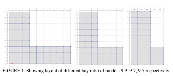
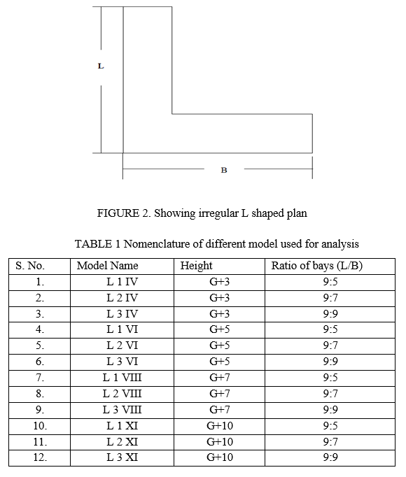
In this work RC frame having irregular plan arrangement are designed as per capacity-based criteria. The models include four totally different heights of G+3, G+5, G+7 and G+9. For analysis of arrangement of irregularity, “L” formed of planned arrangement having the variation of ratio of length to width (wings) i.e., 9:5, 9:7, 9:9 has been taken. The frame fulfils the planning provisions of various codes like IS 456: 2000, IS 1893: 2016 (Part 1) and IS 13920: 2016. For seismic demand prediction and performance analysis of structure, nonlinear static (Push over) analysis has been carried out. Result are being analyzed on parameters like hinge results, storey drift, torsional ratio and mode vs frequency variation. Analysis is completed with the assistance of ETABS version 19 software package.
A. Merits of Capacity-Based Design
- Ease in design and construction of building frame as compared to building frames having lateral load resisting components.
- Low and medium rise buildings up to 6 stories, can be made seismic resistant without LLRE.
- Ideal construction practice in earthquake prone locations due to its good strength, stiffness and high ductility.
- Facilitate faster construction because of less LLRE installed.
- Meet the demand for a modern trend in architectural design.
- Allows easy structural repair and modification.
- Precisely designed reinforced concrete frame members such as beam and column, prevent brittle failure and promotes ductile behavior, thus catastrophic failure can be ignored.
B. Objectives
In this analysis 12 models of different heights are considered. Models have plan of “L” shaped with variation of length of the wing are proposed. Dynamic analysis (Response Spectrum method) and static nonlinear (push over) analysis is done using ETBAS 19 software. The objectives of this paper are: -
- To understand the effect of strong column weak beam on irregular structure in different parameters such as hinge results of nonlinear analysis, storey drift torsional ratio and mode vs frequency distribution.
- To understand the behavior of hinges generated in irregular structure having strong column weak beam at different level of non-linear states defined as ‘Immediate Occupancy’ (IO), ‘Life Safety’ (LS) and ‘Collapse Prevention’ (CP).
- To understand the seismic performance of capacity based designed irregular structure.
- To analyze the height of irregular structure which can be achieved by having capacity-based design criteria.
II. CAPACITY BASED DESIGN
Capacity design calculation is a concept or method for calculating the flexural strength of a critical section of a structural member based on the hypothetical behavior of a structure to seismic action.
This hypothetical behavior is reflected in the assumption that seismic action is of static equivalent nature and progressively increases until the structure reaches an almost collapsed state, and that plastic hinge joints occur simultaneously at predetermined positions to form a collapse mechanism.
Because the seismic effect is vibrational in nature and the plastic hinges are rather random, the actual behavior of building structures during strong earthquakes is far from what was described above. However, by applying the concept of capacity design to the design of flexural structural members, it is judged that the structure will have adequate seismic resistance that has been demonstrated in many earthquakes in the past.
A characteristic of the load-bearing design concept is the ductility level of the structure, expressed as the displacement ductility factor, or the ductility factor. This is the ratio of the lateral displacement of the structure due to the design earthquake near the collapse to the lateral displacement during the first yielding.
The basis of capacity-based design is based on the concept of strong column and weak beams. The inertial seismic force generated on the floor is transmitted to the ground through various beams and columns. Appropriate components should be ductile. Damage to columns can affect the stability of the entire building, but damage to beams causes local effects. Therefore, it is better to create the beam as a weak link with lesser ductility rather than a column. This method of designing RC buildings is known as the Strong Column Week Beam Design Method.
III. MODELLING AND ANALYSIS
The 3D building model which is based on capacity-based design criteria analyzed using the Response Spectrum method (Linear dynamic analysis) and Push Over analysis (Nonlinear static analysis).
The building models of varying irregularities in wing length having “L” shaped plan of different storey height as G+3, G+5, G+7, G+10 is analyzed using ETABS 19 software. In India, Indian Standard for design of seismic structures IS 1893:2016 is used which is the main standard that provides the outline for the calculation of seismic design forces and for achieving strong column weak beam design concept.
A. Brief Discussion About Modelling Procedure of Capacity-based Design of RC Frame
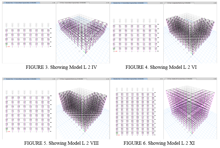
First the general steps are followed in ETABS to made the model for analysis such as defining grids and height of the frame. Then define the materials and section property (beam, column and slab section). Then draw the model and apply the loads as per IS 875: 1987 (Part 1 and 2) for fixed support condition. In the design preferences of concrete frame design, enable the option of P- delta effect and B/C ratio, disable the option of consider additional moments. Then define the mass source of frame system. Then model is analyzed and designed as per IS 456: 2000, IS 1893: 2016 (Part 1) and IS 13920: 2016 for linear static and linear dynamic seismic analysis. Then this model is checked for column beam capacity ratio which should be greater than 1.4 for all joint. After satisfying the column beam capacity ratio for all the joints and members are passed for seismic analysis, push over analysis of displacement control methodology will carry out. In this type of push over analysis procedure first define the dead load as nonlinear static load in load case type. Then define the push in x direction and in y direction of displacement control of 300 mm to 500 mm depends upon the performance point found. Define plastic hinges in beam and column at 10% distance form either side as per ASCE 41-13. After meeting performance point (as per FEMA 440) hinge results are checked for different minimum performance objective (e.g., I.O., L.S., C.P.) as per ASCE 41 and FEMA 356. After hinge results, ductility ratio, moment rotation and back bone curves are analyzed. Different analysis results of linear static and linear dynamic are also analyzed for storey drift and mode vs frequency. Since the frame is irregular in plan torsional analysis is also considered. In the below figures column beam capacity ratio is being shown for different height considered and for irregularity of 9:7.
IV. RESULTS
The dynamic and non-linear static (push over) analysis is conducted on twelve different model using CSI ETABS 19, several values of model were found out from RCC frame which has a property of strong column weak beam. The obtained results are discussed below.
IS 1893-2016, IS 456-2000, IS 13920-2016, FEMA 356 and FEMA 440 guidelines is used for the dynamic and linear static analysis of twelve models of different heights (G+3, G+5, G+7, G+10). These structures are analyzed for ‘L’ shaped plan irregularity with varying bay ratio or wing length (length to width ratio) as 9:5, 9:7, 9:9.
V. FUTURE SCOPE
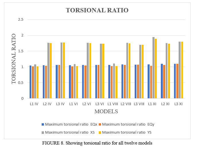
In this study it is shown that irregular of capacity based designed RC frame is being analyzed four different heights and found that torsional ratio is very major concern. All other aspect can be tackled without specific design change. Hence there is vast future scope left in this study which is listed point by point below.
- Capacity-based design of irregular shaped building by considering torsion.
- Explicit design content is unavailable for capacity-based design.
- Role of slab in achieving strong column weak beam is also critical and should analyzed for irregular shaped RC frame.
- Analysis of irregular shaped RC frame which is designed as per capacity based designed criteria with different lateral load resisting element.
- Nonlinear dynamic analysis can also be done to analyze accurate results for hinge formation.
- The follow-up study can be focus on the performance-based design with respect to strong column weak beam criteria.
- Experimental study can be done in the field of relative importance of strong column-weak beam design concept in the multi-story RC frames.
Conclusion
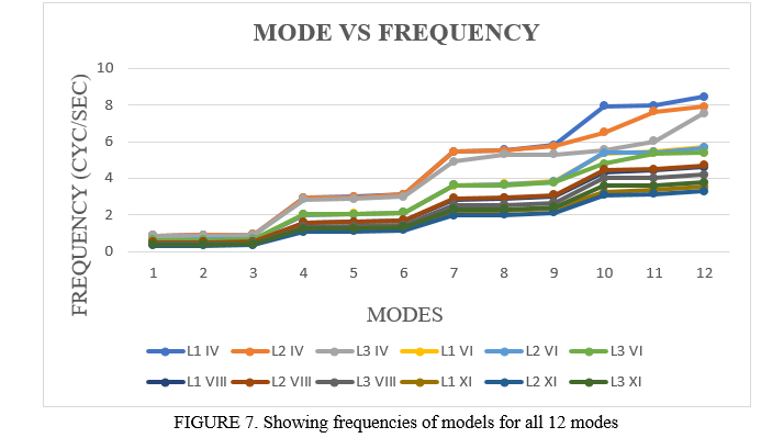
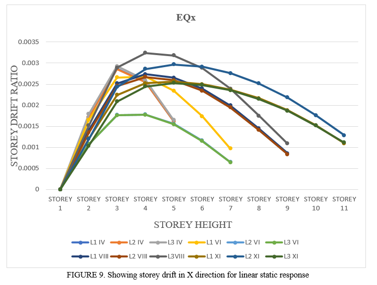
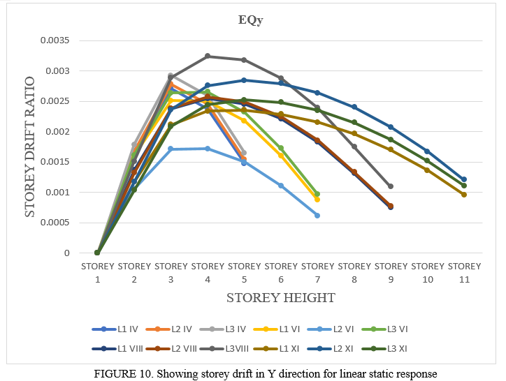
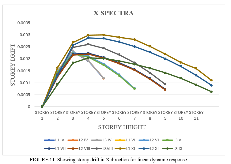
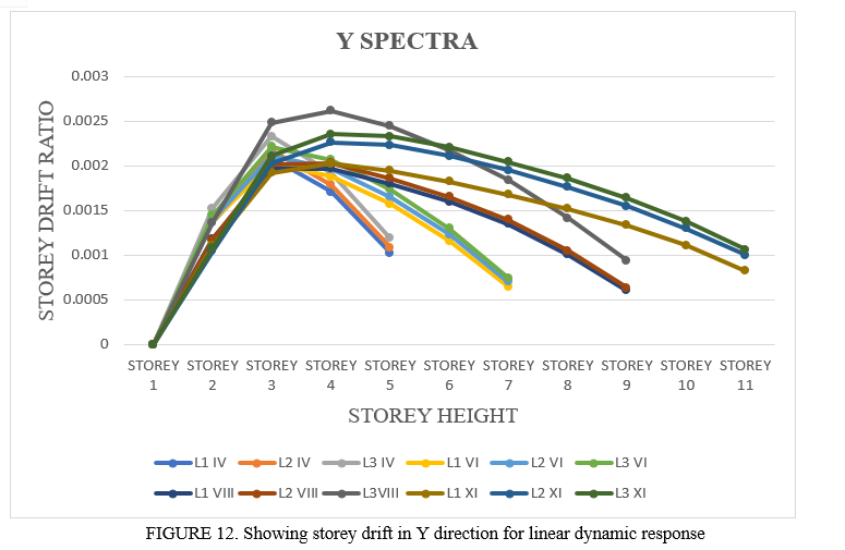
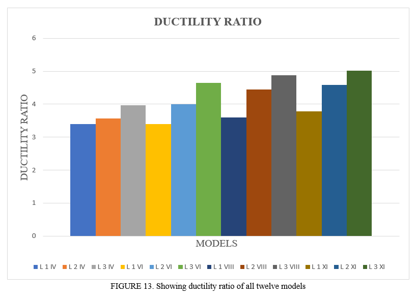
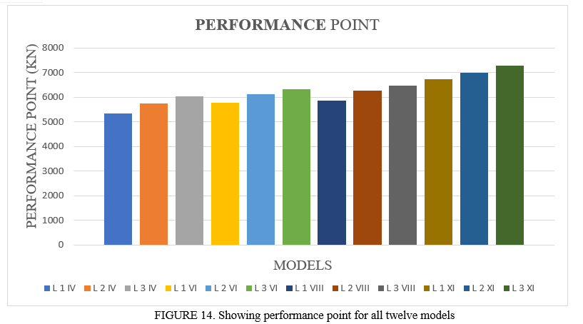
1) Modal Analysis • Frequency of models are decreasing as the irregularity increases. It can be inferred that irregularity doesn’t affect much from modal analysis point of view. • In a similar manner, frequency of models doesn’t affect much as the height of RC frame increases. 2) Torsional Ratio • All twelve models are showing torsional ratio less than 1.5 in static linear seismic analysis. • For linear dynamic analysis for X direction spectral acceleration average increase in torsional ratio for irregularity 9:5 to 9:7 is 3.17% and torsional ratio increment for irregularity 9:7 to 9:9 is 2.24%. • For Y direction spectral acceleration average increase in torsional ratio for irregularity 9:5 to 9:7 is 41.65% and from 9:7 to 9:9 average increment is 1.3%. In Y direction torsional ratio is showing higher increase because of increasing eccentricity i.e., increase in distance between center of mass and center of rigidity. • Height of frame doesn’t make any significant change in the torsional ratio. 3) Storey Drift • For the linear static seismic analysis point of view irregularity and height doesn’t affect the storey drift significantly. • In the linear dynamic analysis, for X spectral acceleration the drift varies with height. Average increase in drift for irregularity 9:5 to 9:7 for four different height frame is 0.5% and for 9:7 to 9:9 is 0.6% which is very nominal change. • In a similar manner, for Y spectral accelaration average increase in drift ratio over four different heigth for irregularity 9:5 to 9:7 is 7.4 % and for irregualrity 9:7 to 9:9 is 4.47%. 4) Ductility Ratio • Push over analysis shows that as irregularity varies from 9:5 to 9:7 the average ductility ratio increases as 16.03% and when irregularity changes from 9:7 to 9:9 the average ductility ratio decreases as 10.17%. It can be inferred that ductility ratio decreases when irregularity increases. • As far as height is being concern the ductility ratio increases 2.1% in G+3 to G+5. For G+5 to G+7 ductility ratio increases as 2.65%. But for G+7 to G+10 the ductility ratio increases as 0.91% only. 5) Performance Point • Static nonlinear analysis shows that average increase in performance point for irregularity of 9:5 to 9:7 is of 5.66% and in 9:7 to 9:9 is of 3.69%. Hence it can conclude that as the irregularity increases average increase in performance point decreases. • In the similar manner performance point shows an increment of 6.07% when comparing G+3 to G+5. From G+5 to G+7 an increment of 8.09% is being observed. At last, for G+7 to G+10 increment in performance point is 11.5%. Thus, by increasing height the performance point also increases. 6) Hinge Results • After analyzing hinge results for models of irregularity type 9:5 is performing better for height of frame up to G+7. After G+7 height the hinge formation doesn’t show the satisfactory results. • For irregularity 9:7, frame satisfying strong column weak beam design mechanism only for height G+3 and G+5 without any lateral load resisting element. • As far as irregularity 9:9 is being concern, frame performing well for capacity-based design only for height G+3 with very high sectional property of column.
References
[1] Sivakumaran K. S. and Balendra T. (1994), “Seismic analysis of asymmetric multistorey buildings including foundation interaction and P-A effects” Engg Struct., Volume 16, Number 8. [2] Juan C., Llera D. L. and Chopra A. K. (1994), “A simplified model for analysis and design of asymmetric-plan buildings” Earthquake engineering and structural dynamics, vol. 24, 573 594, John Wiley & sons, ltd., [3] Wilkinson S. and Thambiratnam D. (2001), “A simplified procedure for seismic analysis of unsymmetrical building” Computer and structure Elsevier science ltd, 2833-2845. [4] Rana R., Jin L. and Zekioglu A. (2004), “Pushover analysis of a 19-story concrete shear wall building” 13th World Conference on Earthquake Engineering, Paper No. 133. [5] Jeong S-H and Elnashai A. S. (2006), “Fragility analysis of buildings with plan irregularities” 4th International Conference on Earthquake Engineering Paper No. 145. [6] Ladjinovic Dj. Z. and Folic R. J. (2008), “Seismic analysis of asymmetric in plan buildings” The 14th World Conference on Earthquake Engineering. [7] Ma H., Liu C., Li Z., Han J., Chen S. (2011), “The Influence of Seismic Input in the Oblique Direction on the Strong-Column Weak-Beam Mechanism for RC Frame”, Advanced Materials Research Vols 243-249 pp 5144-5151 Trans Tech Publications, Switzerland. [8] Khoshnoudian F. and Kiani M. (2012), “Modified consecutive modal pushover procedure for seismic investigation of one-way asymmetric-plan tall buildings” Earthquake engineering and engineering vibration, Vol.11, No.2. [9] Kumar B. G. N., Gornale A. and Mubashir A. (2012), “Seismic performance evaluation of r c-framed buildings - an approach to torsionally asymmetric buildings” IOSR Journal of Engineering (IOSRJEN) ISSN: 2250-3021 Volume 2, PP 01-12. [10] Bai J. & Ou J. (2012), “Plastic Limit-State Design of Frame Structures Based on the Strong-Column Weak-Beam Failure Mechanism”, 15th world conference on earthquake engineering. [11] Sakale R., Arora R K and Chouhan J. (2014), “Seismic behavior of buildings having horizontal irregularities” International journal of structural & civil engineering research, ISSN 2319 – 6009, Vol. 3, No. 4. [12] Sudarsana I. K., Budiwati I. A. M., Aditya P. W. (2014), “Effect of Column to Beam Strength Ratio on Performance of Reinforced Concrete Frames”, ISSN 2407-4330, International Conference on Engineering Technology and Industrial Application. [13] Xinxia L., Maosheng G., Qinghua H., Lili X. (2015), “New Factor to Characterize Mechanism of “Strong Column-Weak Beam” of RC Frame Structures”, 21: 484-491, Tianjin University and Springer-Verlag Berlin Heidelberg. [14] Rajkotia M. N. and Sanghai S. S. (2016), “Seismic analysis of unsymmetrical building using supplemented device” international journal for scientific research & development vol. 4. [15] Daniel D. M. and John S. T. (2016), “Pushover analysis of RC building” International journal of scientific & engineering research, volume 7. [16] Pashine B., Vaidya V. D. and Singh D. P. (2016), “Wind analysis of multistoried structure with T shape and L Shape geometry” International Journal of Engineering Development and Research, Volume 4, Issue 3 ISSN: 2321-9939. [17] Ning N., Qu W. and Ma Z. J. (2016), “Design recommendations for achieving strong column-weak beam in RC frames” Engineering Structures 126: 343–352, http://dx.doi.org/10.1016/j.engstruct.2016.07.053. [18] Mistri A. and Sarkar P. (2016), “Capacity Design of Reinforced Concrete Framed Building for Earthquake Loading”, Indian Journal of Science and Technology, Vol 9(30), DOI: 10.17485/ijst/2016/v9i30/99225. [19] Dnyaneshkumar H., Lanjewar and Khedikar A. (2017), “Seismic analysis of unsymmetrical RCC structures” International journal of innovative research in science, engineering and technology, vol. 6, issn 2319-8753. [20] Mankar N. W. and Pande A. M. (2017), “Understanding Behaviour of T shaped Building under Seismic loading” IOSR Journal of Mechanical and Civil Engineering (IOSR-JMCE), ISSN: 2278-1684, Volume 14, Issue 2 Ver. II. [21] Wongpakdee N. and Leelataviwat S. (2017), “Influence of Column Strength and Stiffness on the Inelastic Behavior of Strong-Column-Weak-Beam Frames”, Journal of Structural Engineering, ASCE, ISSN 0733-9445. [22] Kim J. and Choi Y. (2017), “Seismic Capacity Design and Retrofit of Reinforced Concrete Staggered Wall Structures”, International Journal of Concrete Structures and Materials Vol.11, No.2, pp.285–300. [23] Bento R. and Lopes M. (2018), “Evaluation of The Need for Weak Beam-Strong Column Design in Dual Frame-Wall Structures” 12th world conference on earthquake engineering. [24] Yangbing, Liao Y., Zheng N. & Liu J. (2018), “Analysis of Strong Column and Weak Beam Behaviour of Steel-concrete Mixed Frames” 15th world conference on earthquake engineering.
Copyright
Copyright © 2022 Dev Dutt Chaubey, Dr. Raghvendra Singh. This is an open access article distributed under the Creative Commons Attribution License, which permits unrestricted use, distribution, and reproduction in any medium, provided the original work is properly cited.

Download Paper
Paper Id : IJRASET40634
Publish Date : 2022-03-05
ISSN : 2321-9653
Publisher Name : IJRASET
DOI Link : Click Here
 Submit Paper Online

