Ijraset Journal For Research in Applied Science and Engineering Technology
- Home / Ijraset
- On This Page
- Abstract
- Introduction
- Conclusion
- References
- Copyright
Seismic Retrofit or Rehabilitation of the Structures/Buildings - A Review
Authors: Jaineshwar Verma, Satish Parihar
DOI Link: https://doi.org/10.22214/ijraset.2022.43475
Certificate: View Certificate
Abstract
This research programme provides solutions addressing the comparative absence of a national platform of knowledge and expertise associated with seismic retrofit or rehabilitation of the multi-storey buildings. This will be achieved through two research objectives that define retrofit solutions for building classes differentiated by: • Age and • Construction materials. The knowledge created in this proposal will be embodied in a Seismic Retrofit Manual titled “Assessment and Improvement of the Structural Performance of Buildings”. Dissemination of research findings will be achieved through “Seismic Retrofit Strategies and Solutions for Existing Buildings: Implementation of the retrofit manual within undergraduate and post-graduate structural engineering programs. Uptake of these solutions will provide national benefit through improved community resilience and greater readiness, as seismically retrofitted multi-storey buildings will be safer to occupy during and after a major earthquake. Economic benefit will primarily accrue through prevention of damage to multi-storey buildings and social benefit will result from lives saved. Rehabilitation is defined as the act or process of making possible a compatible use for a property through repair, alterations, and additions while preserving those portions or features which convey its historical, cultural, or architectural values.
Introduction
I. INTRODUCTION
The research is focused predominantly on multi-storey and non-residential structures, as the majority of single-level dwellings in country are expected to perform satisfactorily in a major earthquake due to their comparatively long period and inherent resilience.
In, BIHAR’s earthquake Magnitude: 8.1, Dated 15th January 1934. This earthquake is considered to be one of the worst quakes in Indian history. The epicenter of the earthquake was located in eastern Nepal. Extensive damage was caused to life and property. The intensity of the earthquake was so strong that its effect was felt in Kolkata-650 km from epicentre. Purnea, Munger, Muzaffarpur and Champaran were among the worst-affected areas.
In, GUJARAT’s earthquake Magnitude: 7.7, Dated 26th January 2001. The earthquake occurred at 8:40 AM and lasted for two minutes. Several towns and villages were destroyed in the catastrophe. Being close to the epicentre, Bhuj was among the worst-affected areas including Anjaar, Vondh and Bhachau. Several buildings were damaged or destroyed in the quake. The famous Swaminarayan temple in the city of Bhuj was also partially damaged.
In, MARASHTRA’s earthquake Magnitude: 6.4, Dated 30th September 1993. The quake epicentre was at Killari village in Latur district. Osmanabad and Latur were the worst affected areas. The destruction was massive with over 52 villages completely flattened.
In, ASSAM’s earthquake Magnitude: 8.6, Dated 15th August 1950. The epicentre was located at Rima in Tibet. The quake caused widespread destruction in both Assam and Tibet. It was considered to be among the 10 largest earthquakes of 20th century.
In, UTTARKASHI’s earthquake Magnitude 6.1, Dated 20th October 1991. The quake shook Uttarkashi, Chamoli and Tehri in Uttarakhand and caused extensive damage to property. The tremors of the quake were felt up to Delhi.
In the past, seismic retrofit was primarily applied to achieve public safety, with engineering solutions limited by economic and political considerations. However, with the development of Performance-based earthquake engineering (PBEE), several levels of performance objectives are gradually recognized:
- Public safety only. The goal is to protect human life, ensuring that the structure will not collapse upon its occupants or passersby, and that the structure can be safely exited. Under severe seismic conditions the structure may be a total economic write-off, requiring tear-down and replacement.
- Structure survivability. The goal is that the structure, while remaining safe for exit, may require extensive repair (but not replacement) before it is generally useful or considered safe for occupation. This is typically the lowest level of retrofit applied to bridges.
- Structure functionality. Primary structure undamaged and the structure are undiminished in utility for its primary application. A high level of retrofit, this ensures that any required repairs are only "cosmetic" – for example, minor cracks in plaster, drywall and stucco. This is the minimum acceptable level of retrofit for hospitals.
- Structure unaffected. This level of retrofit is preferred for historic structures of high cultural significance.
II. TECHNIQUES/PROCESSES TO BE USED
There are some common seismic retrofitting techniques falls into several categories:
A. External Post-Tensioning
The uses of external post-tensioning for new structural systems have been developed in the past decade. A large-scale U.S./Japan joint research program, unbounded post-tensioning high strength steel tendons have been used to achieve a moment-resisting system that has self-centering capacity.
Pre-stressing can increase the capacity of structural elements such as beam, column and beam-column joints. External pre-stressing has been used for structural upgrade for gravity/live loading since the 1970s.

B. Base Isolators
Base isolation is a collection of structural elements of a building that should substantially decouple the building's structure from the shaking ground thus protecting the building's integrity and enhancing its seismic performance. This earthquake engineering technology, which is a kind of seismic vibration control, can be applied both to a newly designed building and to seismic upgrading of existing structures. Normally, excavations are made around the building and the building is separated from the foundations. Steel or reinforced concrete beams replace the connections to the foundations, while under these, the isolating pads, or base isolators, replace the material removed. While the base isolation tends to restrict transmission of the ground motion to the building, it also keeps the building positioned properly over the foundation. Careful attention to detail is required where the building interfaces with the ground, especially at entrances, stairways and ramps, to ensure sufficient relative motion of those structural elements.

Fig. Base isolation
C. Supplementary Dampers
Supplementary dampers absorb the energy of motion and convert it to heat, thus damping resonant effects in structures that are rigidly attached to the ground. In addition to adding energy dissipation capacity to the structure, supplementary damping can reduce the displacement and acceleration demand within the structures. In some cases, the threat of damage does not come from the initial shock itself, but rather from the periodic resonant motion of the structure that repeated ground motion induces. In the practical sense, supplementary dampers act similarly to Shock absorbers used in automotive suspensions.
Fig. Supplementary dampers
D. Tuned Mass Dampers
Tuned mass dampers (TMD) employ movable weights on some sort of springs. These are typically employed to reduce wind sway in very tall, light buildings. Similar designs may be employed to impart earthquake resistance in eight to ten story buildings that are prone to destructive earthquake induced resonances.
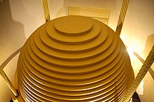
Fig. Tuned mass dampers
E. Slosh Tank
A slosh tank is a large container of low viscosity fluid (usually water) that may be placed at locations in a structure where lateral swaying motions are significant, such as the roof, and tuned to counter the local resonant dynamic motion. During a seismic (or wind) event the fluid in the tank will slosh back and forth with the fluid motion usually directed and controlled by internal baffles – partitions that prevent the tank itself becoming resonant with the structure. A slosh tank is a passive tuned mass damper. In order to be effective the mass of the liquid is usually on the order of 1% to 5% of the mass it is counteracting, and often this requires a significant volume of liquid. In some cases these systems are designed to double as emergency water cisterns for fire suppression.

Fig. slosh tank
F. Active Control System
Very tall buildings ("skyscrapers"), when built using modern lightweight materials, might sway uncomfortably (but not dangerously) in certain wind conditions. A solution to this problem is to include at some upper story a large mass, constrained, but free to move within a limited range, and moving on some sort of bearing system such as an air cushion or hydraulic film. Hydraulic pistons, powered by electric pumps and accumulators, are actively driven to counter the wind forces and natural resonances. These may also, if properly designed, be effective in controlling excessive motion – with or without applied power – in an earthquake. In general, though, modern steel frame high rise buildings are not as subject to dangerous motion as are medium rise (eight to ten story) buildings, as the resonant period of a tall and massive building is longer than the approximately one second shocks applied by an earthquake.

Fig. Skyscrapers
G. Adhoc Addition of Structural Support/Reinforcement
The most common form of seismic retrofit to lower buildings is adding strength to the existing structure to resist seismic forces. The strengthening may be limited to connections between existing building elements or it may involve adding primary resisting elements such as walls or frames, particularly in the lower stories. Common retrofit measures for unreinforced masonry buildings in the Western United States include the addition of steel frames, the addition of reinforced concrete walls, and in some cases, the addition of base isolation.
H. Infill Shear Trusses
Shown here is an exterior shear reinforcement of a conventional reinforced concrete dormitory building. In this case, there was sufficient vertical strength in the building columns and sufficient shear strength in the lower stories that only limited shear reinforcement was required to make it earthquake resistant for this location near the Hayward fault.

Fig. Infill shear trusses
I. Massive Exterior Structure
In other circumstances, far greater reinforcement is required. In the structure shown at right — a parking garage over shops — the placement, detailing, and painting of the reinforcement becomes itself an architectural embellishment.
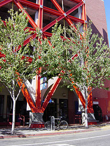
Fig. Massive exterior structure
III. RETROFIT SOLUTIONS
A. Soft-Story failure
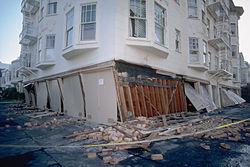
Fig. soft story collapse
This collapse mode is known as soft story collapse. In many buildings the ground level is designed for different uses than the upper levels. Low rise residential structures may be built over parking garages which have large doors on one side. Hotels may have a tall ground floor to allow for a grand entrance or ballrooms. Office buildings may have retail stores on the ground floor with continuous display windows.
Typically, where this type of problem is found, the weak story is reinforced to make it stronger than the floors above by adding shear walls or moment frames. Moment frames consisting of inverted U bents are useful in preserving lower story garage access, while a lower cost solution may be to use shear walls or trusses in several locations, which partially reduce the usefulness for automobile parking but still allow the space to be used for other storage.
B. Beam-column Joint Connections
Beam-column joint connections are a common structural weakness in dealing with seismic retrofitting. Prior to the introduction of modern seismic codes in early 1970s, beam-column joints were typically non-engineered or designed. Laboratory testings have confirmed the seismic vulnerability of these poorly detailed and under-designed connections. Failure of beam-column joint connections can typically lead to catastrophic collapse of a frame-building, as often observed in recent earthquakes.
As a result of these studies it is now known that the typical moment-resisting connection detail employed in steel moment frame construction prior to the 1994 Northridge earthquake had a number of features that rendered it inherently susceptible to brittle fracture.
C. Shear Failure
Floors in wooden buildings are usually constructed upon relatively deep spans of wood, called joists, covered with a diagonal wood planking or plywood to form a subfloor upon which the finish floor surface is laid. In many structures these are all aligned in the same direction. To prevent the beams from tipping over onto their side, blocking is used at each end, and for additional stiffness, blocking or diagonal wood or metal bracing may be placed between beams at one or more points in their spans. At the outer edge it is typical to use a single depth of blocking and a perimeter beam overall.
D. Sliding off Foundation and "cripple wall" failure
Single or two-story wood-frame domestic structures built on a perimeter or slab foundation are relatively safe in an earthquake, but in many structures built before 1950 the sill plate that sits between the concrete foundation and the floor diaphragm (perimeter foundation) or studwall (slab foundation) may not be sufficiently bolted in. Additionally, older attachments (without substantial corrosion-proofing) may have corroded to a point of weakness. A sideways shock can slide the building entirely off of the foundations or slab.
This requires structural grade sheet plywood, often treated for rot resistance. This grade of plywood is made without interior unfilled knots and with more, thinner layers than common plywood. New buildings designed to resist earthquakes will typically use OSB (oriented strand board), sometimes with metal joins between panels, and with well attached stucco covering to enhance its performance. In many modern tract homes, especially those built upon expansive (clay) soil the building is constructed upon a single and relatively thick monolithic slab, kept in one piece by high tensile rods that are stressed after the slab has set. This post stressing places the concrete under compression – a condition under which it is extremely strong in bending and so will not crack under adverse soil conditions.

Fig. sliding off failure
E. Reinforced Concrete Column Burst
One simple retrofit is to surround the column with a jacket of steel plates formed and welded into a single cylinder. The space between the jacket and the column is then filled with concrete, a process called grouting. Where soil or structure conditions require such additional modification, additional pilings may be driven near the column base and concrete pads linking the pilings to the pylon are fabricated at or below ground level. In the example shown not all columns needed to be modified to gain sufficient seismic resistance for the conditions expected. (This location is about a mile from the Hayward Fault Zone.)
F. Damage to Masonry (infill) Walls
To prevent masonry infill damage and failure, typical retrofit strategies aim to strengthen the infills and provide adequate connection to the frame. Examples of retrofit techniques for masonry infills include steel reinforced plasters engineered cementitious composites, thin layers fiber (FRP), and most recently also textile-reinforced mortars (TRM).
G. Utility Pipes and Cables: Risks
There are two primary methods of automatically restraining the flow of gas after an earthquake, installed on the low pressure side of the regulator, and usually downstream of the gas meter.
- A caged metal ball may be arranged at the edge of an orifice. Upon seismic shock, the ball will roll into the orifice, sealing it to prevent gas flow. The ball may later be reset by the use of an external magnet. This device will respond only to ground motion.
- A flow-sensitive device may be used to close a valve if the flow of gas exceeds a set threshold (very much like an electrical circuit breaker). This device will operate independently of seismic motion, but will not respond to minor leaks which may be caused by an earthquake.
H. Underwater Tubes
The safety of underwater tubes is highly dependent upon the soil conditions through which the tunnel was constructed, the materials and reinforcements used, and the maximum predicted earthquake expected, and other factors, some of which may remain unknown under current knowledge.
Conclusion
A. Reasons of Failure 1) Improper construction site on a foothill. 2) Poor detailing of the reinforcement (lack of concrete confinement in the columns and at the beam-column joints, inadequate splice length). 3) Seismically weak soft story at the first floor. 4) Long cantilevers with heavy dead load. B. Preventions 1) To minimize possible losses, construction process should be organized with keeping in mind that earthquake may strike any time prior to the end of construction. 2) Each construction project requires a qualified team of professionals who understand the basic features of seismic performance of different structures as well as construction management. Key factors for the improved seismic performance of adobe construction are: • Quality of construction. • Compact, box-type layout. • Seismic reinforcement 3) The use of timber framing in buildings provides their complete skeletal framing which offers some structural benefits as the timber frame, if properly engineered, lends it to better seismic survivability. 4) Special provisions for seismic load-resisting systems for all engineered wood structures requires consideration of diaphragm ratios, horizontal and vertical diaphragm shears, and connector/fastener values. In addition, collectors, or drag struts, to distribute shear along a diaphragm length are required. 5) To prevent catastrophic collapse in response earth shaking (in the interest of life safety), a traditional reinforced concrete frame should have ductile joints. Depending upon the methods used and the imposed seismic forces, such buildings may be immediately usable, require extensive repair, or may have to be demolished. 6) Prestressed structure is the one whose overall integrity, stability and security depend, primarily, on a prestressing. Prestressing means the intentional creation of permanent stresses in a structure for the purpose of improving its performance under various service conditions. 7) For structural steel seismic design based on Load and Resistance Factor Design (LRFD) approach, it is very important to assess ability of a structure to develop and maintain its bearing resistance in the inelastic range. A measure of this ability is ductility, which may be observed in a material itself, in a structural element, or to a whole structure.
References
[1] Bozorgnia, Yousef; Bertero, Vitelmo V. (2004). Earthquake Engineering: From Engineering Seismology to Performance-Based Engineering. CRC Press. ISBN 978-0-8493-1439-1. [2] \"Earthquake Engineering - an overview | ScienceDirect Topics\". www.sciencedirect.com. Retrieved 2020-10-14. [3] Geotechnical Earthquake Engineering\". earthquake.geoengineer.org. [4] Seismology Committee (1999). Recommended Lateral Force Requirements and Commentary. Structural Engineers Association of California [5] Omori, F. (1900). Seismic Experiments on the Fracturing and Overturning of Columns. Publ. Earthquake Invest. Comm. In Foreign Languages, N.4, Tokyo [6] Network for Earthquake Engineering Simulation\". Official web site. Archived from the original on September 28, 2018. Retrieved September 21, 2011. [7] Base isolation for earthquake engineering\". YouTube. 2007-06-27. Archived from the original on 2021-12-21. Retrieved 2012-07-31 [8] Passive and active vibration isolation systems – Theory\". Physics-animations.com. Retrieved 2012-07-31. [9] neesit (2007-07-10). \"LBRtest\". YouTube. Archived from the original on 2021-12-21. Retrieved 2012-07-31. [10] Building Technology + Seismic Isolation System – Okumura Corporation\" (in Japanese). Okumuragumi.co.jp. Archived from the original on 2012-08-25. Retrieved 2012-07-31 [11] Housner, George W.; Jennings, Paul C. (1982). Earthquake Design Criteria. EERI [12] Earthquake-Resistant Construction\". Nisee.berkeley.edu. Archived from the original on 2012-09-15. Retrieved 2012-07-31. [13] Archived copy. Archived from the original on 2008-10-26. Retrieved 2008-06-19. [14] Farzad Naeim, ed. (1989). Seismic Design Handbook. VNR. ISBN 0-442-26922-6. [15] Arnold, Christopher; Reitherman, Robert (1982). Building Configuration & Seismic Design. A Wiley-Interscience Publication. ISBN 0-471-86138-3. [16] Template for External Caltrans Pages\". Dot.ca.gov. Retrieved 2012-07-31. [17] Strategy to Close Metsamor Plant Presented | Asbarez Armenian News\". Asbarez.com. 1995-10-26. Retrieved 2012-07-31. [18] Neesit. \"Niigita Earthquake 1964 – YouTube\". www.youtube.com. Retrieved 2012-07-31. [19] Robert W. Day (2007). Geotechnical Earthquake Engineering Handbook. McGraw Hill. ISBN 978-0-07-137782-9. [20] Nuclear Power Plants and Earthquakes\". World-nuclear.org. Retrieved 2013-07-28. [21] Soil Liquefaction with Dr. Ellen Rathje\". YouTube. Archived from the original on 2021-12-21. Retrieved 2013-07-28. [22] Tsunami disaster (Sri Lanka Resort)\". YouTube. Archived from the original on 2021-12-21. Retrieved 2013-07-28. [23] Robert Lark, ed. (2007). Bridge Design, Construction and Maintenance. Thomas Telford. ISBN 978-0-7277-3593-5. [24] Bad construction cited in quake zone – World news – Asia-Pacific – China earthquake | NBC News\". NBC News. Retrieved 2013-07-28. [25] Earth Architecture – the Book, Synopsis\". Retrieved 21 January 2010. [26] Shake table testing of adobe house (4A-S7 East) – YouTube\". Nz.youtube.com. 2007-01-12. Archived from the original on 2021-12-21. Retrieved 2013-07-28 [27] Timber Design & Construction Sourcebook=Gotz, Karl-Heinz et al. McGraw-Hall. 1989. ISBN 0-07-023851-0. [28] Rossen Rashkoff. \"Reinforced Brick Masonry\". Staff.city.ac.uk. Archived from the original on 2013-08-19. Retrieved 2013-07-28. [29] Ekwueme, Chukwuma G.; Uzarski, Joe (2003). Seismic Design of Masonry Using the 1997 UBC. Concrete Masonry Association of California and Nevada. [30] Nilson, Arthur H. (1987). Design of Prestressed Concrete. John Wiley & Sons. ISBN 0-471-83072-0. [31] Nawy, Edward G. (1989). Prestressed Concrete. Prentice Hall. ISBN 0-13-698375-8. [32] Seismic Design Manual. Chicago: American Institute of Steel Construction. 2006. pp. 6.1–30. ISBN 1-56424-056-8. [33] EERI Endowment Subcommittee (May 2000). Financial Management of Earthquake Risk. EERI Publication. ISBN 0-943198-21-6. [34] Eugene Trahern (1999). \"Loss Estimation\". Archived from the original on 2009-04-10. [35] Craig Taylor; Erik VanMarcke, eds. (2002). Acceptable Risk Processes: Lifeline and Natural Hazards. Reston, VA: ASCE, TCLEE. ISBN 9780784406236. Archived from the original on 2013-01-13. [36] 1994 Building Publications – Status of the U.S. Precast Seismic Structural Systems (PRESSS) Program [37] skymetweather.com [38] Lowes & Moehle (1998) – ACI Structural Journal Vol 96(4) – pp 519–532 [39] Experimental testing of external post-tensioning for retrofit of RC beam-column joint [40] Pollini, Nicolò; Lavan, Oren; Amir, Oded (2016-03-01). \"Towards realistic minimum-cost optimization of viscous fluid dampers for seismic retrofitting\". Bulletin of Earthquake Engineering. 14 (3): 971–998. doi:10.1007/s10518-015-9844-9. ISSN 1573-1456. [41] Beres, A., Pessiki, S., White, R., and Gergely, P. (1996). [42] Implications of experimental on the seismic behaviour of gravity load designed RC beam-column connections. Earthquake Spectra, 12(2), 185–198. [43] Calvi, G. M., Moratti, M., and Pampanin, S. (2002). Relevance of beam-column damage and collapse in RC frame assessment. Journal of Earthquake Engineering, 6(1), 75–100. [44] Park, R. (2002). A Summary of Result of Simulated Seismic Load Tests on Reinforced Concrete Beam-Column Joints, Beams and Columns with Substandard Reinforcing Details. Journal of Earthquake Engineering, 6(2), 147–174. [45] Holmes WT, Somers P. Northridge earthquake Reconnaissance Report. Supplement C, vol. 2. Earthquake Spectra. 1996(11):1–278. [46] Park R, Billings IJ, Clifton GC, Cousins J, Filiatrault A, Jennings DN, et al. The Hyogo-ken Nanbu Earthquake of 17 January 1995. Bull of New Zealand Soc of earthquake Eng. 1995;28(1):1 -99.
Copyright
Copyright © 2022 Jaineshwar Verma, Satish Parihar. This is an open access article distributed under the Creative Commons Attribution License, which permits unrestricted use, distribution, and reproduction in any medium, provided the original work is properly cited.

Download Paper
Paper Id : IJRASET43475
Publish Date : 2022-05-28
ISSN : 2321-9653
Publisher Name : IJRASET
DOI Link : Click Here
 Submit Paper Online


