Ijraset Journal For Research in Applied Science and Engineering Technology
- Home / Ijraset
- On This Page
- Abstract
- Introduction
- References
- Copyright
Self Balancing Robot
Authors: Sonu Verma, Omprakash Rajankar
DOI Link: https://doi.org/10.22214/ijraset.2024.45580
Certificate: View Certificate
Abstract
Self-regulation robot is among the demainding topic and the working principle behind it is widely used in the humanoids, transportation and robotic hands in industries for improvemising the capaibility and features. In this project, we are working on the layout, control mechanisum, and draft of self-propelled robot. The robot is equipped with stepper motor, PID controller, accelerometer and gyroscope that are used to measure the robot motions and along the x and y axis. In addition, we have focused on the mathematical modeling and simulation of robot. This robot is designed to use analog data to control vehicle speed efficiently. This data is used to feed variation in the pulse width of the motor to reset the robot angle to zero.
Introduction
I. INTRODUCTION
A standard robot with two wheels can described as a inverse pendulum. Inverted pendulum are ubiquitous and a self-propelled device that is likened the human body while the human’s body looks like a pendulum on the ankle. Modern self balancing systems are becoming increasingly popular, often used in robotics arms, transportation and within companies, many such emerging compnies in the market like amazon, self balanced systems are taking over the world. In addition, these two-wheeled simulation systems pave the way for new robots, especially auxiliary robots, due to their ease of operation and operation.
Several good examples of self balanced robots can be seen now a day, one among them is HITACHI EMIEW, a robot built into a two-wheeled simulation system. This robot can navigate on busy and narrow roads take important decisions like it can detect and avoid obstacles. Designed for interect with human’s and even it communicate with them using the features of artificial intelligence.
II. STRUCTURE FOR SELF-BALANCING
This robot's structure is divided in 3 parts: sensors feedback, drive control, and the PID controller. Sec II-A describes purpose, benefits and future scopes of gyroscope and accelerometer used in the robot, as well as ways this gyro, accelerometer and the PID MCU are used to acquire acceleration, motion, and direction information.
A. Sensor selection and applications
Data about the robot’s inclination angle and rotation speed are required to balance robot. All the data required to balance the robot is done by utilizing Micro ElectroMechanical System(MEMS) devices such as a gyro and a free fall( accelerometer) sensor decoder.
The gyroscope is a sensor that can monitor the balancing robot's angular velocity and deliver feedback to the PID controller. The MPU6050 Gyroscope is utilised in this robot, which delivers data to the PID controller via I2C protocol and has the advantages of three-axis angle measurements (even though one axis data is needed for balancing), lower waste of energy and relatively inexpensive compare to other modules available. In fact, angular velocity integration directly yields the inclination angle; although, this technique incorporates clatter in the gyros reading. In view of this, magnitude of θ varies. The complementary filter technique is used to compensate for angular drift in Section III-A. freefall sensor utilized to evaluate exterior velocity on the balancing robot, which includes horizontal and the translational accelerations on the robot. Gyroscope (MPU6050) used in the project, and it has characteristics like threeaxis tracking, voltage output regulation, and affordable cost. X-axis and Z-axis movement readings is being used to conclude the inclination angle θ using the direction cosine approach. Although this approach provides quick results, it is sensitive to adverse influences and disturbances.
B. Stepper Motors and Driver Module
1) NEMA-17 Stepper Motor
Because it must counter the rotating momentum that working on bot, the balancing robot's motor selection prioritises torque output rather than velocity. As a result, the motors must deliver adequate force to return back the body of bot to a self-balanced position. As per some rough estimate, maximal force needed to correct the robot from a 20-degree inclination,
The faceplate of a NEMA-17 stepper motor is (1.7 × 1.7) inches, and it normally provides more torque than other options. This stepper motor contains 6 line wiring and of 12 volt voltage rating and this stepper can also run at low power level, but again the motor-torque will be reduced. As names says stepper motors doesn’t revolve; instead, it rotate in steps, and this NEMA17 stepper motor takes 1.8 degrees of step in a single move, which means that every step covers 1.8 degree course. The step angle of a stepper motor is used to compute the sequence of iterations per revolution for that stepper motor. As a result, the NEMA17 step angle in this case is 1.8 degrees.
2) A-4988 Motor Drive:
A4988 motor driver is a segment stepper controller module used in bi-directional stepper-motors. this A4988 drive board has a integrated converter, one can control the drives with two lines of PID microcontroller i.e. “direction” and “steps” pins of this A4988 stepper motor drive. This “STEP” line is for regulate the steps movement, and this “DIRECTION” line handles the motor's directions. The A4988 drive also supports full-step, haft-step, quarter-step, eight-step, and sixteenth-step drive rates.
C. Ardiuno Nano V3 Control Board
1) Provision of electricity
This Arduino-Nano V3 can power-up with just a usb port of pc, a (6-20v) unfilterd power source on 30th pin or a 5v controlled supply on 27th pin. The maximum power source automatically chosen as input source to the device.
2) RAM and ROM Memory
The ATmega328 employed in the board has 32KB flash memory, 2KB assigned to boot and this ATmega328 had serial-RAM and EEPROM of 2KB and 1KB respectively.
3) Input/Output Ports
Digitalwrite, digitalRead and pinModes functions are available, every digital pin onboaded in Nano is being used as an I/O pin. These pins are driven on 5v input voltage. these pins incorporates (20-50k?) inbuilt pull-up resistors ( remains open collertor initially) and may works on a max of 40mA. additionally, several other pins are for specialized roles:
- PWM: 6 analog pin avail can be used by analogWrite() method one can generates 8-bit pulse width modulation.
- SPI: MOSI, MISO, SS and SC pins, support SPI protocol, which backed by the operating system, is not yet supported by the Arduino language.
Arduino Nano has eight analogue inputs pins, those pins have a 10bits resolution (it means 1024 non-identical data can be processed). it measure and compare data between GND to 5v in default scenario, but higher end of the range can be altered through analogReference() component. Analog pins 6 and 7 are fixed analogue pins only. otherwise some pins also have some other specific functions
4) Communication protocol support:
The ATmega328P MCU empoyed in Nano V3 has a various type of comm. protocol support to connect it to external world like a another Arduino board, or anyother type of mcu’s or computer/laptops. It is compatible with a UART (serial) communication. via digital pins RX and TX. This communication is routed over a usb-port using FT232RL chip available on the Ardiuno boards and drivers for FTDI are already available on the Arduino IDE support package, it also provides a com-port on the IDE. This Arduino IDE includes a serial interface for rx/tx of simple text message in bi-dirfectional manner with Arduino board. Whenever any data is transmitted via FTDI chip onboarded and Usb interface to the machine, RX and TX LEDs embedded onboard started flashes up. S/W based serial libraries are also available which enables the serial data transfer on any digital pin of Ardiuno board. SPI and I2C protocols are also supported by the Ardiuno. To use the TWI interface Arduino package includes a Wirelibrary. ATmega328 datasheet can be refer for more information on communication protocol supports or any other feature.
III. ANGLE EXTRAPOLATION AND STABLIZATION
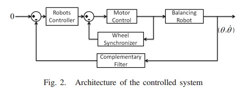
The The self-balancing robot's system architecture is depicted in Fig. 2, PID controller passes a stepper motor control command, and an feedback signal for motor syncing. response of wheels is feeded via complementry filter, which quantifies the robot inclination angle based on gyroscope reading. In this section, we will first discuss the angle extrapolation, then synchronization mechannisum for motors and the mechannisum for balancing the bot.
A. Angle Extrapolation
We studied in Sec II, A gyro is employed to conclude angle movement of device from balanced position, while an free-fall sensor calculates the Y-axis and Z-axis movements of the device. The inclination position of the bot is reverted to the upright position i.e. balanced state by using wheels movement on same direction of inclination. This necessitates a precise count of inclination angle θ. Gyroscope is the simplest way to obtain the angle; since the gyros gives rotational velocity, concluding that angle on inclination is calculated.
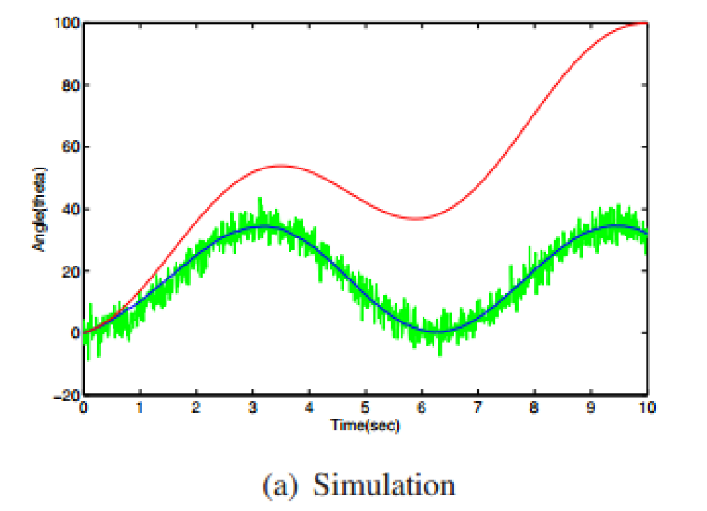 Fig 3: Wheel syncornization pattern
The gyroscope measurement, on the other hand, contains noise. As a result, the other methodology integrate not only rotational acceleration nevertheless, there is also noise components added to the system. This causes calculated data to deviate from original angle value. Apart from this directioncosine approach can also be implemented on the calculated data concluded by free-fall sensor is another option. to obtain θ instantaneously; however, noise and the robot's increasing velocity will also alter this.
To tackle the correct angle calucation problem, we applied a complement filtering technique that makes decisions based on average movements, as illustrated in Fig. 2. The complementary filter utilises the gyro values as the input to conclude the noise in the robot's angle motion.
B. Wheel-Synchronization using Inner-loop Control
Ideally, Both motors should revolve at the same speed if the identical drive signal is delivered to the motors drive circuit. However, in the actual world, there are a variety of reasons why the motors moves at diff-diff speeds even with the similer signals, including motor faults, terrain, and ground obstructions. As a result, a method for synchronising of both drives is necessaity. To solve this we designed a drive synchronising mechanisum having a simpler PI controller as shown in Fig: 4. This mcu manage the pulse width modulation inputs of drives so the errors among them the manages the error. Fig: 5 depicts the outcome of experiments on motors travel data without and with the drive syncing module, As a result, it is evident that wheel synchronisation works.

Fig 4: Block diagram of wheel syncornization
C. Vibrant Model designing :
A dynamical model is first constructed in order to generate a balanced robotic interface. The linear system model that goes with it is drawn from nonlinear models of similar robots that have been published in the literature. [3], [4], [5].
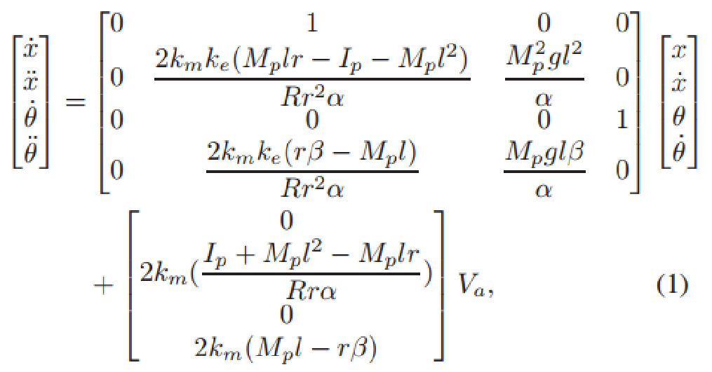
where x? and x is the horizonal movement(m) and speed (m/s) of robot's CG, respectively. θ is the angle of inclination in radian, ?=ω is rate of angular change in rad/s; where Va denotes the voltage applied to the motor V. The following are the model parameters:
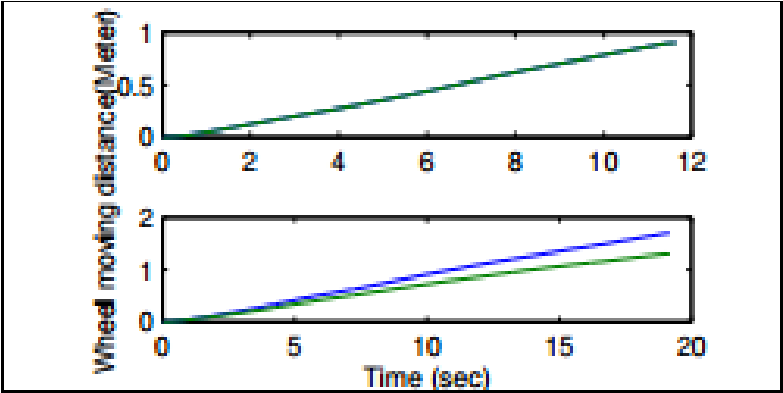
Fig 5: distance travel by wheels.
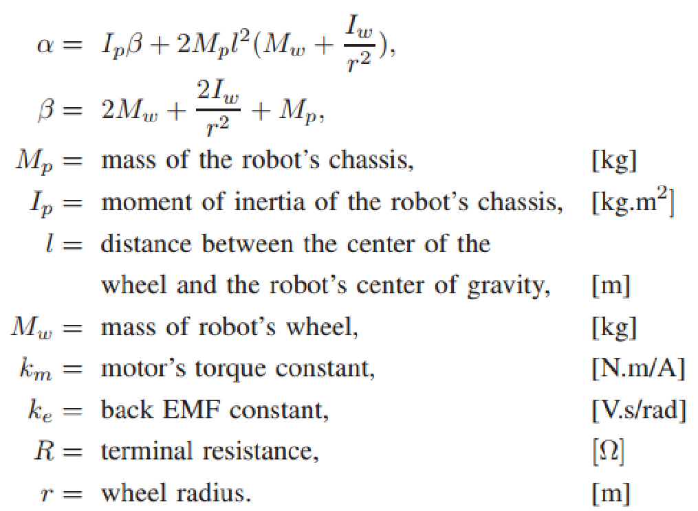
Experimentally, the above physical properties are determined using mechanical operations (e.g., using a trifilar pendulum technique) or electrical observations. The outcomes can be seen on the table below:

Centre of gravity movement can’t be directly calculated in real. Instead, encoders can be used to monitor wheel movement z and velocities v. The state variables in (1) are connected to these measurement outputs by

D. Designs for Balancing Control:
Two control design strategies according to linear quadratic regulator design are investigated in this paper PID PI-PD control [4].
1) PID Controller
PID control is the key approch that has been explored and widley utilised in range of current industrial approches. PID controller was chosen as it is simple to apply, and there are text-book design approaches available for it

Fig 6: A balanced robot control flow
PID MCU's component layout is depicted in Fig 5, with the complement filter giving estimates of rotational speed and inclination angle of device. controlling in different ways is achieved by the accumulating a ‘w’ value with Kd (i.e. differential gain) instead of the transforming the angle count done, that would exacerbate noisy data level. The corosponding controlling is obtained by multiplying θ with the Kp(proportional gain), furthermore the integral control is obtained by numeric integral and multiplying by the Ki(integral gain). Using this inclination angle θ as the result, this model (1) may be used to construct the transfer function from Va to θ:
A PID’s transfer fn can be written like:
where sum of z1 + z2 = Kp/Kd, multiple of z1z2 = Ki /Kd, and K = Kd. As a result, PID design can be done by multiplying the L(s)(loop gain) = G(s)C(s) by 2 zeros and origin’s pole, then estimating controlled gain K using analysis of root-locus theory. Zeros are being used in this design:
The closed-loop poles can be observed entering given a large enough gain K, the open left-half-plane. With a dampingratio of 1 and gain (K) = 0.61 is obtained.

Fig 6: Block diagram of balancing robot
IV. EXPERIMENTAL COMPARISON
An experiment is carried out to compare the PI-PD and PID controllers. The results is in Fig. 7 show that PID control has just a minimal effect on stability: After 25 seconds, angular oscillations surpass the motors' torque limit and cannot be contained. Furthermore, as a result of C.G. During balancing, the robot's position slips due to misalignment. PIPD control, on contrary, achieves significantly better stability than PID controlling mechnasium. Furthermore, PI-PD controlling can be varies the centre of gravity misalign data and returning of the bot to its original position i.e. balanced state.
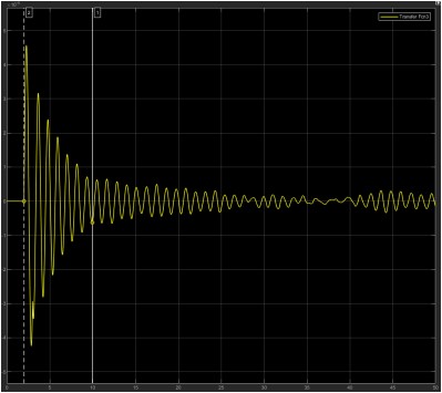
Fig 7: Response with time in balancing robot’s angle
V. FINAL REMARKS ON THE PROJECT
We used low-cost components to build a self-balanced robot, and for the balancing while in motion, we created a inclination-angle predictor and a stabilising (PI-PD) controller. Some future upgrade goals are listed below.
- Improved mechanical design: The centre of mass will have to be repositioned as a result of improved mechanical design, improved sensor positioning, adjustment of complementing filter to eliminate displacement-induced distortion, With a solid control system for improved balancing action
- Remote Controlling of device: The robot can be equipped with communicating protocols or devices such as Wifi, Zigbee, Laura allowing users to manage its position from distance and examine the information via sensors. Users commands actions such as streight, backwards, left and right are also possible.
- Avoiding halting blocks: To tackle more sophisticated applications, such as avoiding obstacles and more controlled operation, the procerror design might be combined with other devcies such as UV and IR sensor, camera, digital compass, GPS and many more.
References
[1] R. Fierro, F. Lewis, and A. Lowe, “Hybrid control for a class of underactuated mechanical systems,” IEEE Transactions on Systems, [3] Man and Cybernetics, Part A: Systems and Humans, vol. 29, no. 6, [4] pp. 649–4, nov 1999. [2] K. Xu and X.-D. Duan, “Comparative study of control methods of single-rotational inverted pendulum,” in Proceedings of the First International Conference on Machine Learning and Cybernetics, vol. 2, 2002, pp. 776–8. [3] F. Grasser, A. D’Arrrigo, S. Colombi, and A. C. Rufer, “JOE: A mobile, inverted pendulum,” IEEE Transactions on Industrial Electronics,vol. 49, no. 1, pp. 107–14, 2002. [4] D. P. Anderson. (2003, Aug.) nBot balancing robot. Online. [Online]. Available: http://www.geology.smu.edu/ dpa-www/robo/nbot [5] R. C. Ooi, “Balancing a two-wheeled autonomous robot,” Final Year Thesis, The University of Western Australia, School of Mechanical [14] Engineering, 2003. [6] N. M. A. Ghani, F. Naim, and P. Y. Tan, “Two wheels balancing robot with line following capability,” World Academy of Science, M. J. A. Arizaga, J. de la Calleja, R. Hernandez, and A. Benitez, “Automatic control for laboratory sterilization process rsd on Arduino [19] hardware,” in 22nd International Conference on Electrical Communications and Computers, 130-3, Ed., 2012. [7] S. Krivic, M. Hujdur, A. Mrzic, and S. Konjicija, “Design and implementation of fuzzy controller on embedded computer for water level control,” in MIPRO, Opatija, Croatia, May 21–25 2012, pp. 1747–51. [8] V. Georgitzikis and I. Akribopoulos, O.and Chatzigiannakis, “Controlling physical objects via the internet using the Arduino platform over 802.15.4 networks,” IEEE Latin America Transactions, vol. 10, no. 3,
Copyright
Copyright © 2024 Sonu Verma, Omprakash Rajankar. This is an open access article distributed under the Creative Commons Attribution License, which permits unrestricted use, distribution, and reproduction in any medium, provided the original work is properly cited.

Download Paper
Paper Id : IJRASET45580
Publish Date : 2022-07-13
ISSN : 2321-9653
Publisher Name : IJRASET
DOI Link : Click Here
 Submit Paper Online

