Ijraset Journal For Research in Applied Science and Engineering Technology
- Home / Ijraset
- On This Page
- Abstract
- Introduction
- Conclusion
- References
- Copyright
Self Balancing Rover using PID Control
Authors: Prof. Jitendra Gaikwad, Vinit Mundhada, Hrucha Nagre, Hrutvij Patil
DOI Link: https://doi.org/10.22214/ijraset.2024.65509
Certificate: View Certificate
Abstract
Two wheeled self-balancing robot, which is based on an inverted pendulum system, is dynamically stable but statically unstable. The robot uses a variety of control theories and physical principles. This project ex plains how to model a two-wheeled self-balancing robot, uses PID to design the robot controller, and installs the controller on the robot. It comprises both equipment and programming usage. A nonexclusive feedback controller (PID Controller) is used to locate stable inverted positions. Mechanical Model made up of two BO motors, MPU6050, one Arduino microcontroller , L298n Motor driver as an elementary need. The parameters determine the expected external force to raise the robot and are also considered system parameters. It remained upright by applying wheel acceleration in accordance with its tilt from vertical to horizontal.
Introduction
I. INTRODUCTION
It comprises both equipment and programming usage. A nonexclusive feedback controller (PID controller) is used to locate its stable inverted position.
Since its invention, the two-wheeled self-balancing robot's substantial nonlinearity and unstable dynamic performance have made it a hot topic in the evaluation of various control theories. In addition to its independence, it also has the benefits of a small size and a straightforward construction, which suit it for certain dangerous or confined operations. Overall, the two-wheeled self-balancing robot is a practical piece of civilian and military technology and an appropriate platform for experimenting with various control algorithms.
The Inverted Pendulum model (IP) serves as the foundation for the self-balancing robot. An inverted pendulum robot with two wheels must have its live tilt angle measured to maintain equilibrium. To correct the tilt, a second controller is required. The system is unstable and non-linear with a single input signal and multiple output signals. It is very difficult to balance an inverted pendulum without exerting external force on the system. The pendulum angle can be changed using a PID-controller because the system is a Single-Input Single-Output (SISO). MIMO systems need more than one PID controller because they allow the robot's x-position and angle to be changed. A state space controller facilitates multistate control. The "Inverted Pendulum" model, which describes a system where an inverted pendulum must be kept upright by moving the wagon it is attached to under its center of mass, serves as the foundation for the design of a self-balancing robot. This concept was expanded upon to create a robot that needed to drive its base of support under its center of mass in order to balance itself on two wheels and align itself perpendicular to the ground.
The inverted pendulum has attracted the attention of many scientists and engineers because of its instability, high order multi-variables, nonlinear and strong coupling characteristics and mobility
II. LITERATURE REVIEW
The industrial revolution is best illustrated by the development of the self-balancing robot. This project will see significant improvement in the days to come. The inverted pendulum theory gave rise to the idea of self-balancing. A PID controller, gyroscope, accelerometer, and obstacle sensor were used in the construction of the robot. The PID controller must be manually adjusted to obtain the best values. Its accuracy level will be raised in order to increase its steadiness and fluidity of movement. It is possible to integrate a two-wheel robot with the framework to transport loads under a variable burden condition. It is possible to use the KALMAN filters as an indicator and estimator. Using the pole area, the strength was evaluated. A mobile robot typically consists of more than three legs and a basic mechanical structure; however, because leg robots have more degrees of freedom in their design, they are more difficult to construct. The need for control systems in our daily lives is becoming more and more necessary due to the growing need for automation and to reduce human error. To comprehend the benefits and drawbacks of the PID algorithm—which is the best control theory available—a model was created.
Applying the fundamental ideas of engineering mechanics, electronics, programming, and control theory, the mechatronic system of a self-balancing robot was successfully designed and built, and it operated with a remarkably high degree of accuracy.
Due to the physical constraints of the actuators (mainly gear backlash) and sensors (update rate), the robot's performance analysis revealed expected behavior along with a few minor undesired oscillations and very slight errors in state estimation. Selecting carefully constructed sensors and actuators will help you easily avoid these flaws.
A two-wheeled self-balancing robot's dynamic model and control schemes are presented in this paper. The dynamic model of the two-wheeled self-balancing robot under investigation is computed using the Newtonian method, and the control strategies are developed in accordance with the dynamic model that is computed and created specifically for this paper. Tilt angle and displacement are the parameters of the proposed robot that are used to control the proposed robot. Proportional derivative and proportional integral derivative controllers are designed based on the location of the system zeroes and poles, which are determined using the transfer functions of the robot under study. The genetic algorithm is used to fine-tune the controllers' parameters. Fuzzy logics are applied to enhance balance, particularly in the presence of external forces. The suggested robot's body experienced a slight vibration, according to the experimental results of implementing the proportional derivative controller, and it eventually collapsed. The suggested robot's stability was increased by the proportional integral derivative controller, but when an outside force was applied to its body, the robot collapsed. The two-wheeled self-balancing robot under study exhibits impressively improved stability under external forces following the implementation of the designed Fuzzy-PID controller.
III. METHODOLOGY
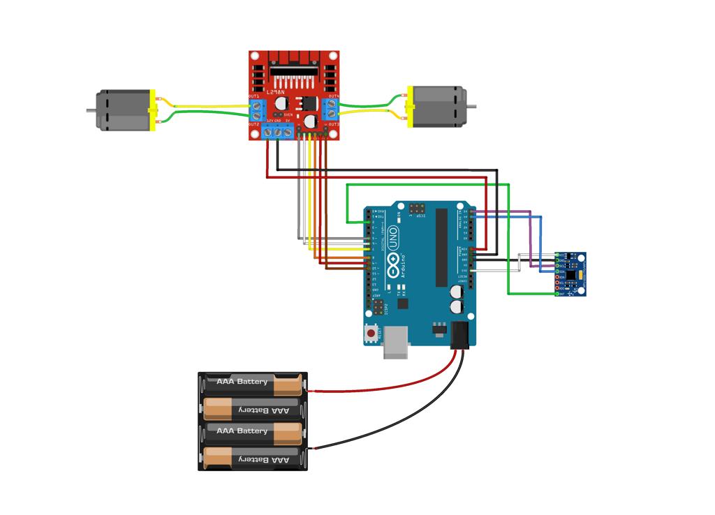
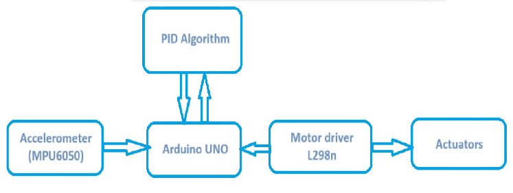
The methodology of this project is divided into two parts namely the mechanical design and the software algorithm. e. The process includes building the base and body of the robot. This is followed by software algorithm implementation and hardware integration. Finally, the robot will be tested and fine-tuned for performance improvement. The project include components such as Arduino UNO, L298n Motor driver , MPU6050 , BO motors and Battery 12v . The project is based on PID Control. The software part i.e Code of Arduino is done on Arduino IDE.
A. PID Controller
The PID (Proportional Integral Derivative) controller method system has been used in this project. PID controller is a closed-loop system, often known as a feedback control system. This control system, which uses a fixed point to evaluate feedback variables, creates an error every time. After that, it modifies the output of the computer system. As long as the error numbers remain zero, the procedure continues. With just two control states and a considerably more fluctuating nature than an on/off controller, PID controllers generate outputs that are perfectly aligned with their target values, whereas on/off controllers create outputs that are slightly incorrect.
1) P Controller
P-controller generates an output proportion to present error. By comparing the desired set point with actual value, the control multiplies proportional constant with resulting error to get the output value. If the value is zero, the output becomes zero. A manual reset is required when used alone. This is due to the fact that it is never in a constant state of functioning. Stable-state mistake is inevitable. Increases in response value are caused by a rise in proportionate gain.
2) I-Controller
I-controller is required due to the restriction of P controller, where there is always an error between the process variable and the setpoint, which is used to demean steady-state error. Over time, it integrates the error until it approaches zero. When a negative error is produced, Integral Control declines, which slows down the robot's response time and affects its sound quality. By decreasing Integral gain, k, the speed of the response diminishes.
3) D-Controller
The I-controller does not have the ability to forecast incorrect behavior in the future. As a result, when the setpoint is modified, it reacts normally. D-controller solves this problem by anticipating the error's future behavior. The derivative constant multiplied by the error rate over time determines its output, improving the system responsivity being given a boost at the start. It responds faster and settles outputs quicker than PI-based controllers, increasing the system's stability by accounting for the I-phase controller's lag. By raising the derivative gain, the response time is speed up.
B. Arduino UNO
Arduino UNO is a low-cost, flexible, and easy-to-use programmable open-source microcontroller. The Arduino Uno is a microcontroller board based on the ATmega328. It has 20 digital input/output pins (of which 6 can be used as PWM outputs and 6 can be used as analog inputs), a 16 MHz resonator, a USB connection, a power jack, an in-circuit system programming (ICSP) header, and a reset button.
1) L298n Motor Driver
The L298N is a dual H-Bridge motor driver which allows speed and direction control of two DC motors at the same time. The module can drive DC motors that have voltages between 5 and 35V, with a peak current up to 2A.
C. MPU6050
Magnetic pickup (MPU) sensors are devices which can be used in conjunction with electronic control modules for monitoring parameters such as speed, direction of rotation and a variety of alarm conditions. MPU6050 is a three-axis accelerometer and three-axis gyroscope Micro Electro-mechanical system (MEMS). It aids in the measurement of velocity, orientation, acceleration, displacement, and other motion-related features.
D. BO Motor
BO (Battery Operated) Motor is lightweight DC geared motor which gives good torque and rpm at lower voltages. This motor can run at approximately 100 rpm when driven by a single Li-Ion cell. A BO motor is a type of electric motor that is powered by a rechargeable battery. These are commonly used in portable devices and vehicles, as they offer the convenience of cordless operation.
 Fig no. 01: Circuit Diagram of System

Fig no. 02: Block Diagram
IV. RESULTS AND DISCUSSION
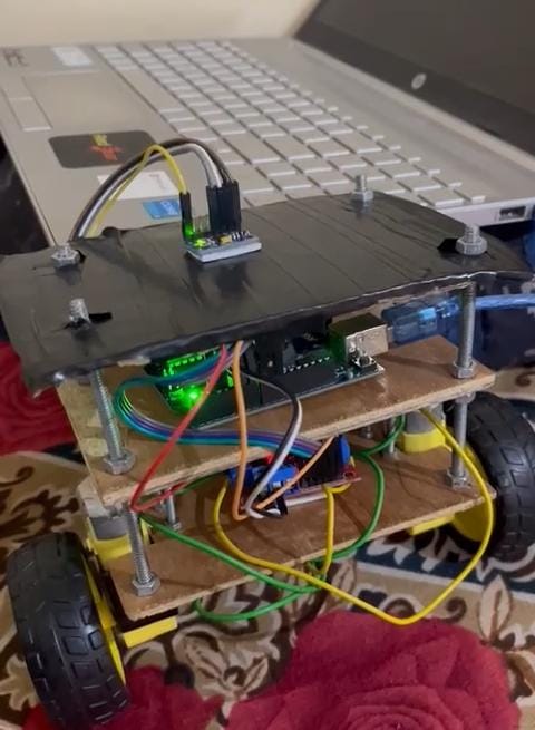
Balancing performance is a crucial aspect of the project because it indicates how effectively the PID control system, sensors, and motors work together to keep the rover upright. The project's primary objective is to achieve self-balancing. The rover balances itself by moving its wheels in a frontal direction when its body tilts forward, which causes the rover's body to move backward and achieve balance.

Fig no: 02 Self Balancing Bot
V. FUTURE SCOPE
The self-balancing rover project, utilizing PID control and various sensors, offers an exciting platform for exploring and advancing several areas of technology and robotics. Its future scope is vast, and it can lead to various developments and applications. Integrate AI assistants or chatbots to enhance interaction and communication capabilities. For example, the rover could provide assistance in smart homes or customer service applications. Incorporate wireless communication to control and monitor the rover remotely. This can enable teleoperation, data transmission, and real-time feedback.
Employ the self-balancing concept in industrial applications for tasks like warehouse automation, inspection, and surveillance. Explore the possibility of commercializing the project by developing a product or service for specific markets, such as home automation, education, or entertainment. Implement the rover for agricultural purposes, such as monitoring crop health, delivering small loads, or performing precision farming tasks.
Conclusion
The primary goal of the project was to design and build a self-balancing rover using PID control. The project\'s success can be measured by the rover\'s ability to maintain balance and stabilize itself on two or more wheels. The project involves various fields, including robotics, control systems, sensor integration, programming, and electronics. The project can be customized and adapted to suit a wide range of applications. Depending on goals, we can take it in different directions, from autonomous navigation to industrial automation or even entertainment. Developing the rover involves addressing challenges related to sensor calibration, control algorithms, and mechanical design. Overcoming these challenges hones problem-solving skills.
References
[1] Avishek Das , Mizanur Rahman , Abidur Rahman Adib ,Mohammad Rahat Anam “Self-Balancing Robot With PID Controller \", International Conference on Mechanical Engineering and Renewable Energy 2021 [2] Chinmay Samak “ Design of A Two-Wheel self-Balancing Robot With the Implementation of A Novel State Feedback for PID Controller using On-Board State Estimation Algorithm”, International Journal of Robotics Research and Development, 2018 [3] Rasoul Sadeghian, Mehdi Tale Masouleh “ An experimental study on the PID and Fuzzy-PID controllers on a designed two-wheeled self-balancing autonomous robot” 4th International Conference on Control, Instrumentation, and Automation (ICCIA) 2016 . [4] Suhardi Azliy Bin Junoh “ TWO-WHEELED BALANCING ROBOT CONTROLLER DESIGNED USING PID” 2015
Copyright
Copyright © 2024 Prof. Jitendra Gaikwad, Vinit Mundhada, Hrucha Nagre, Hrutvij Patil. This is an open access article distributed under the Creative Commons Attribution License, which permits unrestricted use, distribution, and reproduction in any medium, provided the original work is properly cited.

Download Paper
Paper Id : IJRASET65509
Publish Date : 2024-11-25
ISSN : 2321-9653
Publisher Name : IJRASET
DOI Link : Click Here
 Submit Paper Online

