Ijraset Journal For Research in Applied Science and Engineering Technology
- Home / Ijraset
- On This Page
- Abstract
- Introduction
- Conclusion
- References
- Copyright
SEPIC Based BLDC Motor Control for Electric Vehicles
Authors: Dr. Y. Mastanamma, A. Archana, Dr. B Laxman, K. Pulla Reddy, E. Saidulu
DOI Link: https://doi.org/10.22214/ijraset.2024.64946
Certificate: View Certificate
Abstract
This paper presents a BLDC motor that can be utilized in electric vehicle applications where speed control is necessary. It is driven by a single-ended primary inductive converter (SEPIC). The inverter that feeds the motor uses PWM-based switching; however, a SEPIC converter in the DC link can be used to adjust the voltage level. Electronic commutation gating pulses are provided to the inverter input and the DC input. It is effective for electric vehicles since it uses a converter that switches to manage voltage. The SEPIC is lightweight and suitable for use with small electric cars. This paper describes using a SEPIC converter to drive a BLDC motor. The BLDC motor\'s closed-loop speed control is modelled using MATLAB /SIMULINK, and the simulation\'s outcomes are presented.
Introduction
I. INTRODUCTION
Torque has been obtained for electric vehicles using a variety of motor types. For electric vehicles, however, motors that are efficient and capable of producing torque across a broad speed range are favored. For certain electric cars, BLDC motors make sense because they don't lose energy as heat. Because there is no sparking and no need for brushes, it also produces less electromagnetic interference than a DC motor. A Voltage Source Inverter (VSI) is used to create a rotating magnetic field using BLDC coils. To regulate the speed of the BLDC, the VSI needs to be switched on time. The BLDC motor is fed by VSI, which uses pulse width modulation, or PWM. Nonetheless, motor speed control can also be effectively achieved by signaling the SEPIC converter and managing the voltage level.
II. SEPIC CONVERTER
A DC-DC power converter is the SEPIC converter. One kind of buck-boost converter is this one. Because this process involves ripples, it uses inductors to store and transfer energy from one level to another. A capacitor is then utilized to eliminate the ripples. Electronic switches such as a diode and Metal Oxide Field Effect Transistor (MOSFET) are used to perform the switching operation. The input and output of the SEPIC converter have the same polarity. Because it can function in both continuous and discontinuous conduction modes, the SEPIC is versatile. This work proposes a discontinuous conduction mode SEPIC converter.
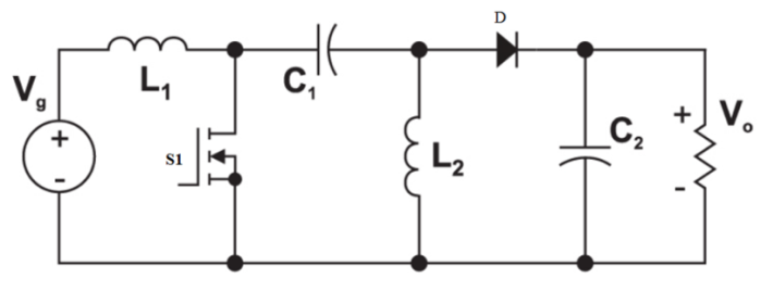
Fig.1.Circuit of SEPIC
As illustrated in Fig. 1, the SEPIC converter circuit consists of the following components: load resistance, diode D, two inductors, L1 and L2, coupling capacitor C1, and output capacitor C2. The input and output circuits of SEPIC converter circuits are connected by a common ground. This converter transforms the input DC voltage to the desired output voltage level by exchanging energy between the inductor L1, capacitor C1, and inductor L2. To regulate how much energy is exchanged, a power transistor switch (S1), like a MOSFET, is typically utilized.
Key benefits of SEPIC Converters: The SEPIC converter has advantages over a traditional buck-boost converter, including better efficiency, superior input current purity, and non-inverting output voltage.
The SEPIC converter has advantages over a flyback converter (isolated buck-boost) that uses a transformer for isolation. These advantages include lower switching losses, lower output voltage noise, higher efficiency, and the ability to operate at a high frequency.
A. Discontinuous Conduction mode operation of SEPIC
In this conduction mode, the current flowing through the inductor at the output side is discontinuous during switching time, and the voltage across the capacitor which is in a series connection remains continuous. Three operating states are there during the switching period of the converter.
- Mode I: (switch on): When the switch turns on, currents in the inductors rise, and the capacitor on the output side discharges, providing power to the motor. The diode is inactive during this mode.
- Mode II (switch off): When the switch is off, the input side capacitor charges up, and current from the inductors passes through the diode. Additionally, there is a rise in voltage across the main power capacitor.
- Mode III: The input inductor keeps discharging while the output inductor completely discharges in this last step. The output capacitor powers the motor while the input side capacitor continues to charge.
III. PROPOSED SEPIC CONVERTER BASED BLDC DRIVE
The SEPIC converter uses a diode bridge rectifier to transform single-phase AC power into a regulated DC voltage. Before the SEPIC converter, an unregulated rectifier is employed. An inverter (VSI) is then used to supply power to the BLDC motor using this DC voltage. This system is unique in that it measures the DC voltage only, i.e., its actual voltage using a single voltage sensor to control the voltage. As a result, power factor correction on the AC supply side is possible. Indirectly, the motor speed is controlled by the SEPIC converter.The primary function of the inverter is low-frequency electronic commutation, which reduces the inverter's internal switching losses. This design's overall performance has been evaluated at different running speeds, torque levels, and situations.
A. Bridge Rectifier
Four diodes are essentially placed in a particular way to form the diode bridge rectifier. At the rectifier's output, a filter is made up of a capacitor (C) and an inductor (L). This filter aids in removing any last waves or variations in the DC voltage. The SEPIC converter then receives the resulting stable DC voltage with few ripples as its input power.
B. SEPIC
The rectifier, which changes AC power into DC, produces a voltage that isn't exactly constant, but the SEPIC converter can still manage it. This is so that it can control the output voltage even in the presence of fluctuating input. The SEPIC converter does this by operating in a unique mode known as "discontinuous conduction mode."
C. BLDC motor and VSI
The direction and speed of the motor are primarily controlled by the VSI. It accomplishes this in two methods: one is modifying the DC link's voltage (which is supplied by the SEPIC converter) and the other is the use of a method known as pulse width modulation, or PWM, to control the output of the inverter. This VSI does not require constant three-phase phase switching, in contrast to a standard three-phase motor inverter. Rather, it ensures that the motor's torque stays constant in one direction by only energizing the relevant motor phase for a predetermined amount of time.
The technology uses Hall sensors that are installed on the motor to identify the proper phase sequence for activation. These sensors send signals that must be interpreted to determine the location of the motor's magnetic poles.
IV. CONTROL OF CONVERTER AND MOTOR
The BLDC motor and the SEPIC converter are both controlled by this system using a two-part control technique. The SEPIC converter is the subject of one section of the control system. It modifies the output DC link voltage, which in turn modifies the speed of the motor. The BLDC motor itself is managed by the other component, which makes sure it runs as intended. In order to maintain the desired output voltage of the converter, the system uses a single control loop based on "voltage tracking" (see Figure 2 for a block diagram). A reference voltage set for the DC link capacitor (C2) is necessary for this control loop to function.
Vdc=kω (1)
Two voltages are continuously compared by it: The intended voltage level is the reference DC-link voltage (Vref). The DC-link capacitor's real output voltage (Vdc).
The "voltage error signal" (Ve) is computed as the difference between these two voltages. The control system can determine how much to modify the output voltage to match the reference by using this error signal.
Ve=Vref-Vdc (2)
Using the error signal as a guide, this PI controller adjusts itself intelligently. It takes into account two things: Term proportional (P): This responds right away to the error's magnitude. A bigger adjustment results from a larger error. Term for integral (I): This takes into account the duration of the error. Over time, it assists in removing any persistent mistakes. The PI controller determines the "controlled voltage" (Vctrl) by summing these variables. To attain the appropriate DC-link voltage, the MOSFET switch (Q) in the SEPIC converter must be adjusted to a certain extent, which is ultimately determined by this controlled voltage.
VC(k) = VC(k-1)+Kp (3)
{VE(k)-VE(k-1)}+K1VE(k)
In this case, 'k' stands for a particular sample point in time, and the gains for the proportional and integral actions inside the PI controller are denoted by Kp and Ki, respectively. These gains affect how much the PI controller takes into account to remove errors in the past and how forcefully it responds to the current fault.
{ If MC< VC then Q is ON } (4)
{ If MC< VC then Q is OFF } (5)
Qon and Qoff are required pulses for switch Q of SEPIC.
BLDC motors rely on electronic commutation, which is accomplished by the inverter's switching sequence, as opposed to brushed
DC motors, which employ actual brushes to reverse the direction of the current. The smooth and effective passage of current from the DC connection to the motor's stator windings is guaranteed by this control technique.
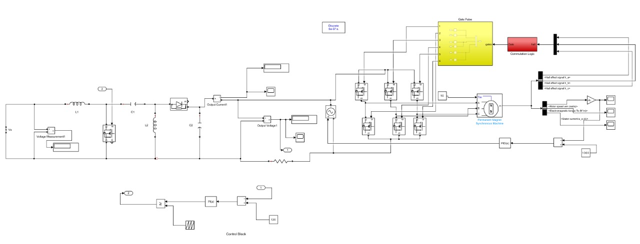 Fig.2.Simulink of SEPIC based BLDC Motor
The inverter requires a precise switching pattern that applies electricity to the appropriate phases at the appropriate times in order to do this. This guarantees a motor that operates at its best and a symmetrical current flow.
The rotor position (spaced 60 degrees apart) of the motor is detected by the system using Hall-effect sensors mounted on it. The signals from these sensors are used to create the electrical commutation pulses that operate the inverter. A line current flows from the DC link capacitor to the motor's stator when certain inverter switches are activated. Numerous variables affect this current's magnitude:
DC link voltage Back-EMFs (motor-generated voltages) and winding resistances Both the windings' mutual and self-inductance. A truth table must be used to decode the Hall sensor data to ensure that the motor operates in the intended direction. This table determines the exact switching order for the inverter based on all the criteria listed.
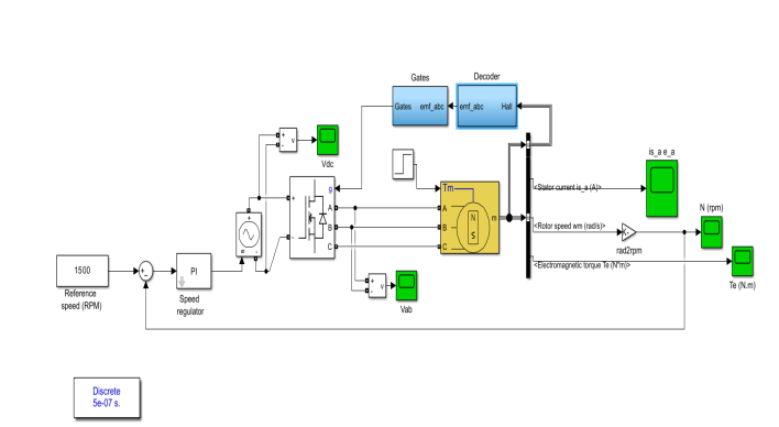
Fig 3: Simulink of BLDC Motor with Electronic Commutation
V. SIMULATION RESULTS AND DISCUSSION
In MATLAB/SIMULINK, a simulation of the suggested BLDC motor system with the SEPIC converter has been performed. The simulation's outcomes are displayed below.
To control the SEPIC converter and guarantee that the DC link voltage remains at the intended level, the system makes use of a control circuit.
Based on the previously described logic, this control produces PWM pulses that turn the converter's switch on and off. This design's capacity to deliver a steady voltage between 50 and 150 volts, regardless of fluctuations in the input voltage, is one of its main advantages. This can be seen in Figure 6, where variations in the input voltage are still accompanied by an output voltage that closely tracks the set point.
As previously stated, the converter is built and programmed to function in a unique mode known as "discontinuous conduction mode." This mode is easily identified by looking at the output inductor's current waveform, which is displayed.
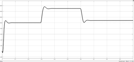
Fig.4. Electromagnetic Torque of BLDC Motor
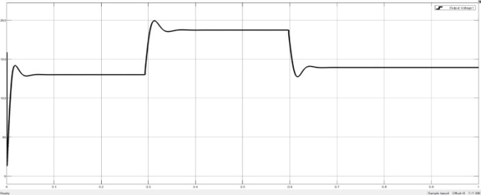
Fig.5. BLDC Motor Speed
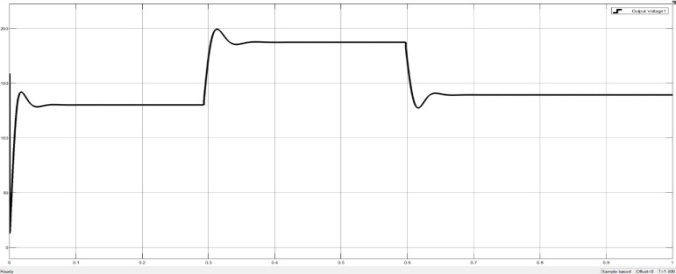
Figure 6: SEPIC variable set points
Conclusion
This novel method of employing a SEPIC converter to control BLDC motors has number of benefits over conventional control techniques. By modifying the DC link voltage of the inverter (VSI) supplying the motor, the system regulates the motor\'s speed. Compared to directly applying pulse width modulation (PWM) on the inverter, this method is more efficient. By employing fixed-width pulses for electronic commutation, the inverter\'s function is reduced to a minimum. To reduce switching losses in the inverter, PWM is solely applied to the MOSFET switch of the SEPIC converter. Enhanced Dynamic Response: By implementing the suggested control strategy, the drive\'s dynamic response is improved, allowing the motor to respond to commands for varying speeds faster. The technology continues to provide the motor with a broad range of regulated speeds. This system requires only one voltage sensor, which lowers overall control expenses as compared to conventional methods. Possibility of Renewable Energy Integration: The suggested drive can be modified to operate with renewable energy sources such as wind turbines or solar panels, which qualifies it for use in electric vehicles, hybrid systems that combine solar and wind energy, and solar-powered pumps.
References
[1] J. V. Rao, L. K. Uttarala, K. K. Vanukuru and S. R. Davu, \"Sepic converter FED BLDC drive with closed loop speed control,\" 2016 International Conference on Signal Processing, Communication, Power and Embedded System (SCOPUS), Paralakhemundi, India, 2016, pp. 1435-1441 [2] Sivaramkrishnan et al., \"SEPIC-Converter Based BLDC-Motor-Drive with Power-Factor-Correction and Minimization in Torque Ripple,\" 2021 2nd International Conference on Smart Electronics and Communication (ICOSEC), Trichy, India, 2021, pp. 726-732, doi: 10.1109/ICOSEC51865.2021.9591741. [3] R.Krishnan: ‘Electric motor drives: modeling, analysis and control’ (Pearson Education, India, 2001). [4] Yang JW, Do HL. Bridgeless SEPIC converter with a ripple-free input current. IEEE Trans Power Electron. 2013;28(7):3388-3394.July [5] B.Singh, V.Bist.: ‘A BL-CSC converter fed BLDC motor drive with power factor correction’, IEEE Trans. Ind. Electron., 2015, 62, (1), pp. 172–183 [6] T.Gopalarathnam, H.A .Toliyat.: ‘A new topology for unipolar brushless DC motor drive with high power factor’, IEEE Trans. Power Electron., 2003, 18, (6), pp. 1397–1404 [7] D.S.L.Simonett, J.Sebastian, J.Uceda.: ‘The discontinuous conduction mode Sepic and Cuk power factor preregulators: analysis and design’, IEEE Trans. Ind. Electron., 1997 [8] H.Y.Kanaan, Al-Haddad, A.Hayek, I.Mougharbel.: ‘Design, study, modelling and control of a new single-phase high power factor rectifier based on the single-ended primary inductance converter and the Sheppard–Taylor topology’, IET Power Electron., 2009.
Copyright
Copyright © 2024 Dr. Y. Mastanamma, A. Archana, Dr. B Laxman, K. Pulla Reddy, E. Saidulu . This is an open access article distributed under the Creative Commons Attribution License, which permits unrestricted use, distribution, and reproduction in any medium, provided the original work is properly cited.

Download Paper
Paper Id : IJRASET64946
Publish Date : 2024-11-02
ISSN : 2321-9653
Publisher Name : IJRASET
DOI Link : Click Here
 Submit Paper Online

