Ijraset Journal For Research in Applied Science and Engineering Technology
- Home / Ijraset
- On This Page
- Abstract
- Introduction
- Conclusion
- References
- Copyright
Comparative Studies on Single Cell and Double Cell Curved Prestressed Box Girder Bridges
Authors: Shaik Irfan, Dr. P. Anuradha
DOI Link: https://doi.org/10.22214/ijraset.2024.63941
Certificate: View Certificate
Abstract
Bridge design has evolved significantly due to increasing spans, necessitating efficient and economical configurations. Cable stayed and suspension bridges are commonly used for long spans, while box girder bridges are suitable for medium and long spans due to their superior flexural and torsional behavior. However, analyzing box girder bridges is challenging due to various structural actions, but judicious selection of preliminary sections can reduce computational effort. This study examines single and double cell curved prestressed Box Girder Bridges under various loads, including class-AA load, class A vehicle load, and prestressed load with variable angle of curvature. The LSM method is adopted instead of working stress method, and numerical models are analyzed using commercially available software (MIDAS Civil). Compared with all the cases, it can be stated that when a bridge is curved in plan, double cell box girder bridges are more effective than single cell box girder bridges. Comparing 120, 150 and 180 curvatures, the 150 curvature is the most appropriate for the length of 36m simply supported girder.
Introduction
I. INTRODUCTION
The worldwide expansion of highway networks is driven by increasing traffic volumes, population growth, and the urban sprawl of metropolitan areas. This growth necessitates changes in bridge design and utilization. Bridge types are chosen based on maximizing efficiency in material use and construction techniques for specific spans and applications. As spans increase, the dead load becomes a significant factor. To mitigate this, excess material that doesn't contribute to structural capacity is removed, leading to the development of box girder or cellular structures, depending on whether shear deformations can be ignored. Box girder bridges offer a larger span range compared to T-beam girder bridges, requiring fewer piers for the same valley width, thereby achieving cost-effectiveness.
A. MIDAS Civil
It is a powerful finite element analysis software designed for bridge engineering, featuring a user-friendly interface and advanced design solutions. It supports sequential form traveler load management and integrates time-dependent material properties like creep and shrinkage. The software adheres to standards such as the CEB-FIP code for calculating member sizes and includes tools like the Structural Wizard for efficient modeling. Additional features include the MCT command shell for advanced commands and bill of quantities for concrete dead load estimation. Elastic links facilitate connections between superstructures and substructures, and the software handles analysis of post-tensioned segmental bridges, considering factors like creep and tension losses. MIDAS Civil supports multiple design codes including IRC, AASHTO LRFD, and EURO code, while alternative software options for bridge analysis include CSI Bridge, STAAD Pro, SAP 2000, and Tekla Structures.
II. LITERATURE REVIEW
Zain Mohd et:al [2022][3]. STAAD.Pro V8i software was utilized to analyze a T-beam bridge using IRC loadings and a logical method approach. The focus was on examining the T-beam and deck slab of the bridge by applying Courbon's method. The analysis involved calculating the bending moment, shear force, and deflection for an 18.25-meter span. A comparison between the manual calculations and the results obtained from STAAD.Pro V8i revealed that the software-based design proved to be more economical.
Kagali et: al [2021][4] The study analyzed T-beam and box girder bridges under moving loads using software and manual methods, comparing IRC loadings and evaluating bending moments and shear forces.
Meghana et:at [2020][5]. This paper analyzes the effects of T-beam and box girder bridges under moving loads using both software and manual methods. It compares IRC vehicle loadings for different spans and validates software results against manual calculations, focusing on bending moments and shear forces.
Apeksha D. Naharkar et: al [2019][6] The paper shows that the Limit State Method (LSM) is more accurate and economical for segmental bridges than the Working Stress Method (WSM), accounting for long-term effects like creep and shrinkage.
Wen Cheng et: al [2019][7] The study used Midas Civil to analyze a PSC box girder bridge, finding that exponential functions best represent axial compressive strength and that time-dependent effects significantly impact stress and deflection.
Gupta et:at [2017][8] The study shows that orthogonal diaphragms reduce structural actions in skew box-girder bridges, nevertheless they might not be used because of construction-related difficulties. It also points out that there are no rules for maximizing the cross-sectional area at various skew angles.
NajlaYas V et:al [2017][9] The paper compares square, rectangular, trapezoidal, and curved box girder cross-sections using ANSYS. Although square sections perform best, they limit road span due to their equal length and depth. Trapezoidal sections are preferred in practice and align well with engineering needs.
JefeenaSali et: al [2015][10] The paper finds that increasing the radius of curvature in box girders reduces deflection, bending moments, and torsion. Sharp curves, especially those with radii below 100 meters, lead to higher torsional moments and should be avoided or adjusted structurally.
A. Aim And Objective Of Work
- To determine which type of girder and at which angle the design will be most economical
- To model and analyse a single cell and double cell curved Prestressed box Girder Bridge.
- To study the response for the parameters like Deformation, Bending Moment and Torsion moment for
- Class-AA tracked loading and Class A wheel load vehicle.
- Prestressed load.
- For fixed span (36m) and variable angle of curvature. (120, 150 and 180).
B. Need Of Present Work
Recent advancements in bridge design and construction address the need for effective and economical configurations for increasing spans. For very long spans, cable-stayed and suspension bridges are preferred, while box girder bridges are ideal for medium to long spans due to their excellent flexural and torsional performance. Single or multi-cell reinforced concrete box girder bridges are now commonly used for overpasses, underpasses, grade separations, and viaducts in modern highways.
The design analysis of a box girder bridge involves a methodical approach to ensure the bridge is safe, functional, and durable. It encompasses initial planning, detailed structural analysis, design verification, and rigorous review processes to achieve an optimal and reliable design
III. METHODODLOGY
The study is primarily focused on conducting a comprehensive analysis of curved prestressed box girder bridges, considering both single-cell and double-cell configurations. The research systematically examines the influence of various load types including dead loads, superimposed dead loads, class-70R and class A vehicle loads, as well as prestressed loads, across a diverse range of curvature angles by using MIDAS Software.
A. Basic Design Data
- Type of Bridge Proposed = Box Girder
- Span of Bridge (c/c of Exp Joints) = 36m
- Carriageway Width= 8m
- Width of Crash Barrier = 450mm
- Overall Depth of the Girder = 1.8m
- Density of concrete= 25 KN/m3
- Density of Wearing Course= 22 KN/m3
- Thickness of Wearing course= 100mm
- Weight of Crash Barrier= 7.2 KN/m
- Type of Cables = 19 T13
- Type of load (Class 70R vehicle load and Class A vehicle load)
- Cross section (single cell and double cell curved box girder section for same span with different angle (120, 150 and 180))
B. Cross Section
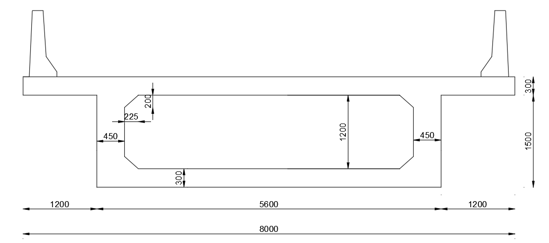 Fig 1: Cross section for single cell Box girder
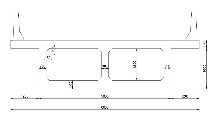
Fig 2: Cross section for Double cell Box girder
C. Creating Model
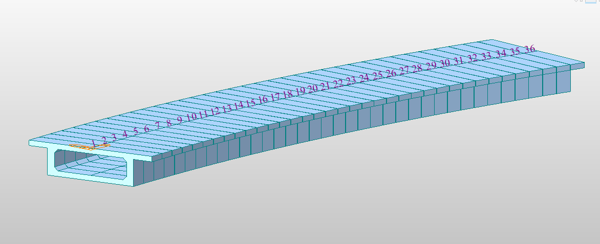 Fig 3: Single cell Box girder
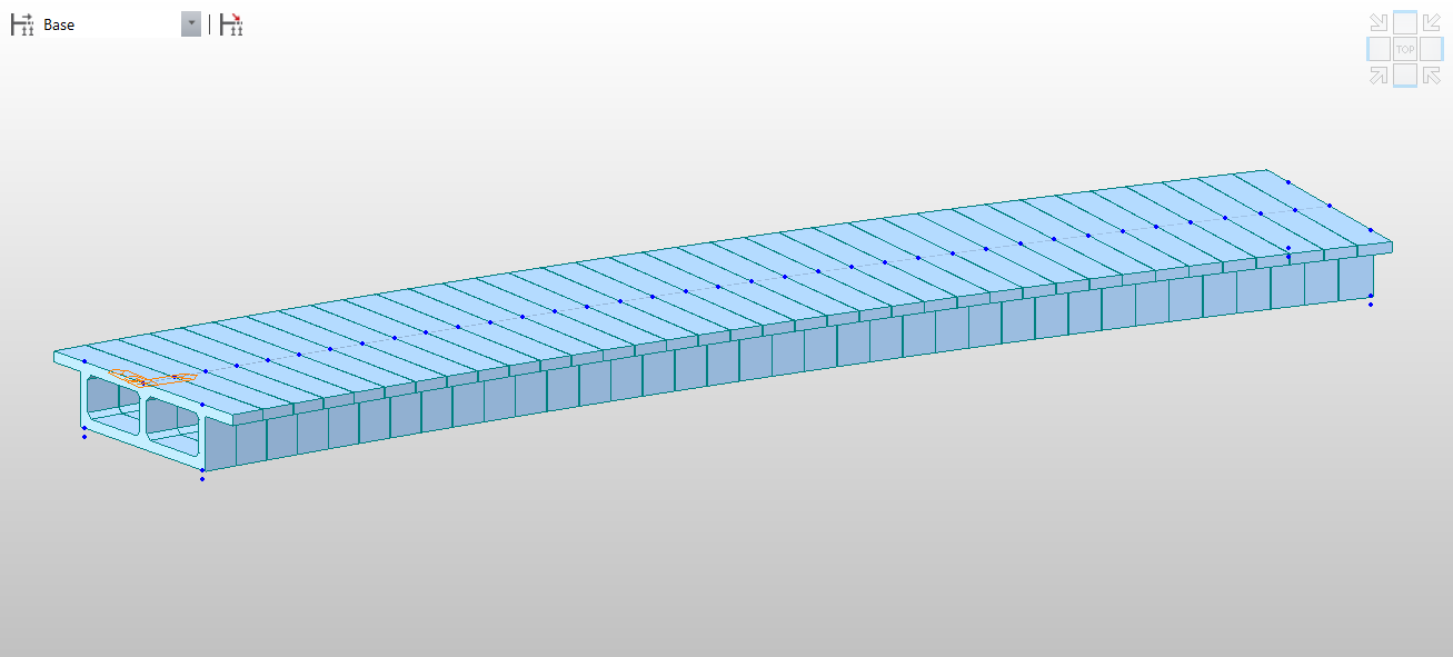 Fig 4: Double cell Box girder
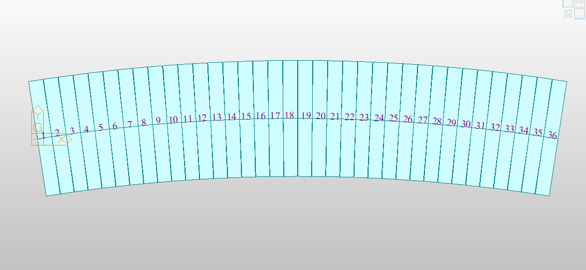 Fig 5: Model of Box girder curved in Plan
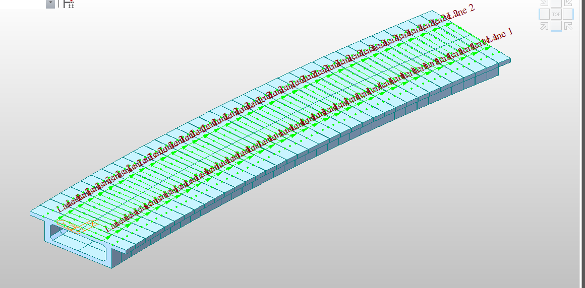 Fig 6: Traffic lane considered for Single Cell Box girder
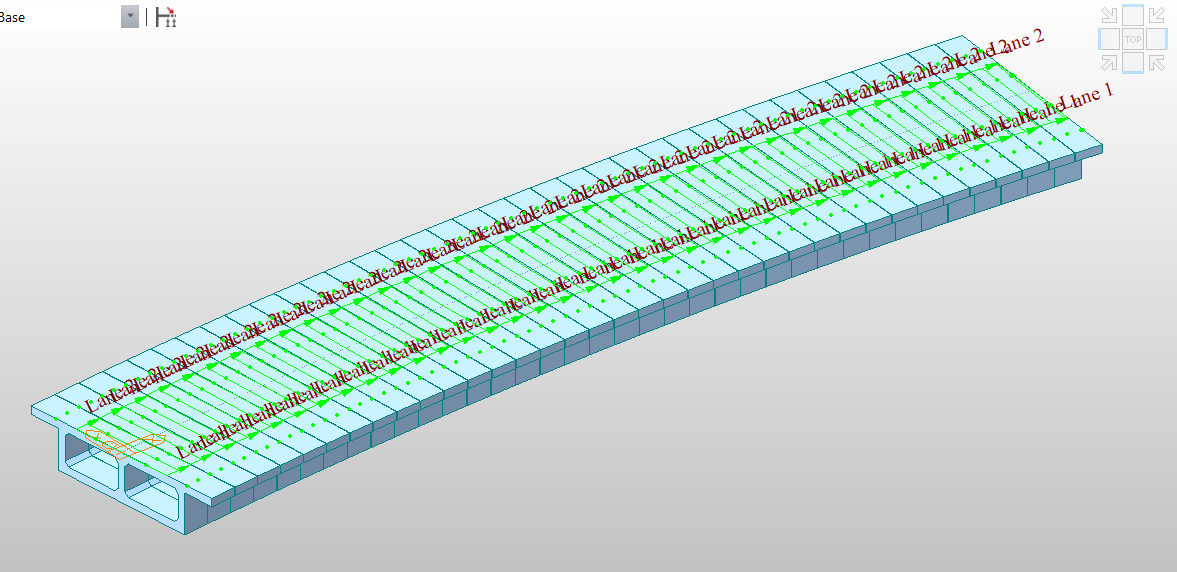 Fig 7: Traffic lane considered for Double Cell Box girder
D. Loads
Dead load: Based on the cross-sectional area, using density of concrete as 25KN/m3, self-weight of the section is arrived at for running sections.
Super imposed dead load:
1) Crash Barrier: According to IRC 5 – 2015 Clause 109.6.3 Details of Crash Barrier for Bridges without Footpath is considered.
Area of Crash Barrier = 0.287125 m2
Crash barrier load = 7.2 KN/m
2) Wearing Course: The thickness of wearing is course is considered as 100mm for the design.
Density of wearing course = 22 KN/m3
Wearing course load = 2.2 KN/m
3) Prestressed load: Post tension load of 200-ton force is applied on each tendon present in the model.
IV. RESULTS AND DISCUSSIONS
The following conclusions are made based on the results obtained from the analysis of single cell and double cell prestressed curved box girder bridge models of simply supported spans using MIDAS Civil (2020). The parameters like Bending moments, Torsional moment and deflections were observed. An attempt is made to study the shear stress for fixed span and fixed width.
A. Maximum Reactions in Single cell and Double cell Box Girders
|
Load Type |
Single cell |
Double cell |
||||
|
SC 12° |
SC 15° |
SC 18° |
DC 12° |
DC 15° |
DC 18° |
|
|
SW |
1464.9 |
1447.5 |
1606.9 |
1464.9 |
1447.5 |
1606.9 |
|
SIDL |
185.3 |
193.9 |
203.2 |
185.3 |
193.9 |
203.2 |
|
MLC |
867.4 |
939.4 |
954.7 |
867.6 |
939.4 |
954.8 |
|
Combination |
3528.9 |
3624.9 |
3875.8 |
3529.1 |
3624.9 |
3875.9 |
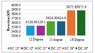
A comparison is done between the maximum reactions for the single cell and double cell box girders, which are curved in plan with different degrees of curvature, under various load combinations such as self-weight, superimposed dead load, moving load case, and total combinations. It is observed that the reactions are almost similar.
B. Maximum Displacement Values in Single Cell and Double Cell Box Girders
|
Load Type |
Single cell |
Double cell |
||||
|
SC 12° |
SC 15° |
SC 18° |
DC 12° |
DC 15° |
DC 18° |
|
|
SW |
21433.15 |
20209.29 |
21526.02 |
21433.15 |
20209.29 |
21526.02 |
|
SIDL |
2710.78 |
2707.62 |
2722.53 |
2710.78 |
2707.62 |
2722.53 |
|
MLC |
935 |
935.05 |
935 |
1395.37 |
1436.41 |
1436.59 |
|
Combination |
8150.19 |
8724.76 |
8785.89 |
8150.2 |
8724.76 |
8785.89 |
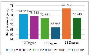
A comparison is done between the maximum displacements in vertical direction for the single cell and double cell box girders, which are curved in plan with different degrees of curvature, under various load combinations such as self-weight, superimposed dead load, moving load case, and total combinations. It has been observed that double cell girders were having lower displacements than single cell girders, and that the 15° angle of curvature has lower displacement than 12° and 18° degrees of curvature.
C. Maximum Shear Force values in single cell and double cell Box Girders
|
Load Type |
Single cell |
Double cell |
||||
|
SC 12° |
SC 15° |
SC 18° |
DC 12° |
DC 15° |
DC 18° |
|
|
SW |
2366.8 |
2230.19 |
2365.44 |
2366.8 |
2230.19 |
2365.44 |
|
SIDL |
299.34 |
298.8 |
299.17 |
299.34 |
298.8 |
299.17 |
|
MLC |
67.77 |
67.07 |
67.54 |
101.65 |
100.61 |
101.31 |
|
Combination |
929.67 |
990.99 |
993.02 |
929.67 |
991 |
993.02 |
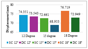
A comparison is done between the maximum Shear force for the single cell and double cell box girders, which are curved in plan with different degrees of curvature, under various load combinations such as self-weight, superimposed dead load, moving load case, and total combinations. It has been observed that for single cell and double cell girders are having similar Shear force and it also observed that with the increase of angle of curvature the Shear force also increasing.
D. Maximum Bending Moment Values in single cell and Double cell Box girders
|
Load Type |
Single cell |
Double cell |
||||
|
SC 12° |
SC 15° |
SC 18° |
DC 12° |
DC 15° |
DC 18° |
|
|
SW |
21433.15 |
20209.29 |
21526.02 |
21433.15 |
20209.29 |
21526.02 |
|
SIDL |
2710.78 |
2707.62 |
2722.53 |
2710.78 |
2707.62 |
2722.53 |
|
MLC |
935 |
935.05 |
935 |
1395.37 |
1436.41 |
1436.59 |
|
Combination |
8150.19 |
8724.76 |
8785.89 |
8150.2 |
8724.76 |
8785.89 |
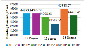
A comparison is done between the maximum Bending moment for the single cell and double cell box girders, which are curved in plan with different degrees of curvature, under various load combinations such as self-weight, superimposed dead load, moving load case, and total combinations. It has been observed that for single cell and double cell girders are having similar Bending moment and it also observed that with the increase of angle of curvature the Bending moment also increasing.
Conclusion
The following conclusions are made based on the results obtained from the analysis of single cell and double cell prestressed curved box girder bridge models of simply supported spans using MIDAS Civil (2020) in the form of maximum Shear force, bending moments, Torsional moment and deflections are noted: 1) Shear force does not increase linearly with an increase in the angle of curvature for single cell and double cell box girders. Specifically, for a 15° angle of curvature, shear force exhibits a slight decrease. 2) The maximum shear force of 5038.13 kN is observed in the single-cell 18° box girder, while the minimum shear force of 4824.91 kN is observed in the double-cell 15° box girder. 3) The bending moment curve for the box girder forms a parabolic shape. Bending moment does not increase linearly with the angle of curvature for both single-cell and double-cell box girders. Specifically, for a 15° angle of curvature, the bending moment shows a slight decrease. 4) The maximum Bending moment of 45988.07 kN.m is observed in the single-cell 18° box girder, while the minimum Bending moment of 42588.56 kN.m is observed in the double-cell 15° box girder. 5) The torsional moment is increasing with increase in angle of curvature for both single cell and double cell box girders. 6) The maximum Torsional moment of 2248.27 kN.m is observed in the single-cell 18° box girder, while the minimum Torsional moment of 1480.12 kN.m is observed in the double-cell 12° box girder. 7) Displacement values does not increase linearly with an increase in the angle of curvature for single cell and double cell box girders. Specifically, for a 15° angle of curvature, displacement values exhibit a slight decrease. 8) The maximum displacement of 76.719 mm is observed in the single-cell 18° box girder, while the minimum displacement of 68.953 mm is observed in the double-cell 15° box girder. Based on the obtained values, it can be concluded that the double cell box girder is more economical than the single cell box girder because it exhibits lower bending moments and displacements for an equivalent cross-sectional area.
References
[1] Meghana, K. V., G. V. Sowjanya, and T. V. Mallesh. \"Review Paper on Comparative Analysis of T-Beam Bridge and Box Girder Bridge.\" [2] Kagali, Vivek N., and Mary Bhagya Jyothi. \"Comparative Assessment of Single-Cell Railway Straight and Curved Box Girder Bridge Using CSI Bridge Software.\" [3] Zain, Mohd, Ashwani Kumar Pandey, Rakesh Varma, and Ranjendra Kumar Srivastava. \"Comparative analysis of T-Beam along with deck slab by Courbon’s method and STAAD. Pro.\" Materials Today: Proceedings 56 (2022): 2261-2267. [4] Gupta, Tanmay, and Manoj Kumar. \"Structural Response of Concrete Skew Box-Girder Bridges.\" International Journal of Bridge Engineering 5, no. 1 (2017): 37-59. [5] Engineering and Technology, Vol. 6, Issue 12, December 2017: 22408-22413. [6] Pathak, Mulesh K. \"Performance of RCC Box type Superstructure in Curved bridges.\" (2014). [7] Sarode, Ashish B., and G. R. Vesmawala. \"Parametric study of horizontally curved box girders for torsional behaviour and stability.\" International Refereed Journal of Engineering and Science (IRJES) 3, no. 2 (2014): 50-55. [8] Menghnani, L., J. S. Pahuja, and C. Sankaralingam. \"Design and construction aspects of a bridge over river Yamuna.\" Indian Concrete Journal 76, no. 11 (2002): 703-711. [9] Sennah, Khaled M., and John B. Kennedy. \"State-of-the-art in design of curved box-girder bridges.\" Journal of Bridge Engineering 6, no. 3 (2001): 159-167. [10] Pandit.G.S and Gupta.S.P, “Structural Analysis – a Matrix Approach”, Tata Mc Graw Hill Publishing Company, 2004. [11] Krishna Raju,N., Design Of Bridges, Third Edition, Oxford & IBH Publishing Company Private Limited, New Delhi, 2004. [12] Raina, V.K., Concrete Bridge Practice – Analysis, Design and Economics, Tata McGraw-Hill Publishing Company Limited, New Delhi, 2003. [13] IRC:5-2015 Standard Specifications and Code of Practice for Road Bridges Section – I, General Features of Design (Eighth Revision). [14] The American Association of State Highway Officials Code, STANDARD SPECIFICATIONS for HIGHWAY BRIDGES 1973. [15] IRC:6-2017 Standard Specifications and Code of Practice for Road Bridges Section-II, Load And Load Combinations (Seventh Revision), The Indian Road Congress, New Delhi, 2000. [16] IRC:112-2020 Code of Practice for Concrete Road Bridges (First Revision), The Indian Road Congress, New Delhi, 2000. [17] IS 14268: Uncoated stress relieved low relaxation seven-ply strand for prestressed concrete, The Indian Road Congress, New Delhi, 2000.
Copyright
Copyright © 2024 Shaik Irfan, Dr. P. Anuradha. This is an open access article distributed under the Creative Commons Attribution License, which permits unrestricted use, distribution, and reproduction in any medium, provided the original work is properly cited.

Download Paper
Paper Id : IJRASET63941
Publish Date : 2024-08-11
ISSN : 2321-9653
Publisher Name : IJRASET
DOI Link : Click Here
 Submit Paper Online

