Ijraset Journal For Research in Applied Science and Engineering Technology
- Home / Ijraset
- On This Page
- Abstract
- Introduction
- Conclusion
- References
- Copyright
Smart Laboratory System Using IOT
Authors: P. Roopa Ranjani
DOI Link: https://doi.org/10.22214/ijraset.2024.65469
Certificate: View Certificate
Abstract
In this fast growing world, the usage of electrical appliances and gadgets has increased due to which the electricity consumption has increased. Being caught in this busy life, people tend to forget things like switching off the electronic devices after usage. This would cause a lot of electricity wastage. If a person recollects that some device is not shut off he needs to leave his current work and reach the device to turn it off manually. This would cause a lot of energy and time wastage. This proposes and analyze a system which is used for energy consumption and monitoring. The system is fully Internet of Things (IoT) based and highly desirable in field of energy. In this system consumer can do power management by knowing energy usage time to time. As the advancement of technology and dependencies over the electrical appliances increased, the usage and requirement of electricity is also increased rapidly. Hence there is a need to reduce the wastage of electricity. The smart laboratory system using IoT helps in monitoring the power consumption regularly. This also helps in controlling various appliances used in the laboratory. This smart system will be helpful in generating the real-time data of the electricity usage. Users will be able to see their daily usage from a web app with the help of their unique identification number and password provided to them at the time of installation of this device. The objective is to make a novel system which will help in reducing the usage and wastage of electricity.
Introduction
I. INTRODUCTION
Everyday devices are made smart and intuitive and by enabling them to share data intelligently they can be used to improve people’s lives. It can be used to provide better personal safety, monitor health, save time and make better use of our natural resources. IoT has made a huge impact in the way people live, work and communicate. Internet of Things (IoT) deals with billions of intelligent objects which would be connected to sense collect the data and also communicate with surrounding people using mobile, wireless and sensor technologies.
Main objective of IoT is to manage and control physical objects around us in a more intelligent and meaningful manner and also improve quality of life by providing cost effective living including safety, security and entertainment. Smart objects gather useful contextual data autonomously and send to remote application servers for offering context aware or location- based services. The word “context” can refer to any location information, surrounding environment, people objects that are nearby etc. so that adaptive and personalized services can be provided to the user. Among many IoT applications, smart homes play an important role in realizing smart cities.
Smart homes can be used for remotely monitoring and controlling electrical appliances. Fitted inside the home using smart intelligent physical infrastructure. The present Government of India (GoI) has proposed to develop 100 smart cities across the country which will create a huge demand for smart home automation solutions in near future. The word “Smart Home” means context aware which can be realized using Information and Communication Technology (ICT) and IoT.
A. Existing System
Over the last few years or it can be said over the last decades, research has been conducted for new devices and technologies to design a good and reliable and efficient system for home automation. Automation technique with Raspberry Pi using IoT Sensors and Systems present a proposed system for Smart Home Automation technique with Raspberry Pi using IoT and it is done by integrating cameras and motion.
To design this system, Raspberry Pi module with Computer Vision techniques is used [1]. Using this system home appliance can be controlled connected through a monitor-based internet. Raspberry Pi operates and controls motion sensors and video cameras for sensing and surveillance. For instance, it captures intruder’s identity and detects its presence using simple Computer Vision Technique (CVT).
Whenever motion is detected, the cameras will start recording and Raspberry Pi device alerts the owner through an alarm call.
Local Networking or by Remote control Home automation is becoming more and more popular day by day due to its numerous advantages. This can be achieved by local networking or by remote control. There paper aims at designing a basic home automation application on Raspberry Pi through reading the subject of the algorithm for the same has been developed in python environment which is the default programming environment provided by Raspberry Pi. Results show the efficient implementation of proposed algorithm for home automation. LEDs were used to indicate the switching action.
Reduction in Cost and Power supply of wireless system Given the reduction in cost and power supply of wireless systems along with the increasing demand for conserving energy when controlling consumer electronics and home appliances, smart home automation systems are more popular than ever before. A home automation system designed for reducing electricity consumption typically uses different sensors located in different areas of the house that communicate with a process unit to control the lights, HVAC system, consumer electronics, etc., so that the process unit turns these systems on only when needed.
II. PROPOSED SYSTEM
The proposed system describes Smart Laboratory System. It also describes the functionality of the different features of the lab automation system.
A. Block diagram
The Smart Laboratory System using IoT has both Hardware and Software. The components used in the project are NodeMCU, Arduino Board, 2 Current Sensors, Digital dimmer module and 2-Relays. There are 3 main functions performed by the project, ON/OFF switching mechanism through relay board, controlling the intensity of the light using web server application, monitoring the current rating of the loads. The main block diagram of the Smart Laboratory System using IoT as shown in the Fig. 2.1.
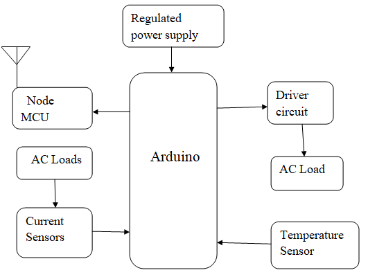
Fig 2.1 Block Diagram of Proposed system
III. WORKING
The propose system works through the web server based application for accessing the devices to turn them ON/OFF, vary the intensity/speed of lamps, fans respectively, monitors the current ratings of the loads and temperature of the laboratory. The application is designed with 3 buttons L1, L2, L3 to access the loads connected to the system and three more buttons to control the intensity/speed of light/fan (LOW, MEDIUM, and HIGH). Arduino Uno plays a main role in passing the instructions to various modules connected to it and then retrieves the useful information like the current and temperature values from Current and Temperature sensors. The Arduino then passes the collected data to NodeMCU module. The NodeMCU has an inbuilt Wi-Fi module(ESP8266) which updates the data in the Application.
The NodeMCU module has an inbuilt regulator which regulates 5 volts to 3.3 volts. This module communicates with Arduino through serial ports.
The A3, A4 pins of Arduino Uno board are used as a serial port communication to NodeMCU module (pin Rx and Tx) and the two way communication is established for taking the sensor readings and controlling purpose. A NodeMCU board needs internet source, so to acts like a router for providing internet through mobile hotspot.
NodeMCU has an inbuilt patch antenna. For accessing the mobile hotspot a user id and password is to be created. These are created in the code dumped into NodeMCU module.
All components are interfaced with Arduino Uno controller. The 6 ADC inputs are used to connect to the analog inputs. The output of the Current sensors are analog, hence are connected to A0 and A1 pins in the Arduino Board Controller. The temperature sensor gives a digital output, hence connected to D2 pin of the Arduino Uno.
The Controller has one Crystal Oscillator used to generate external clock signals of 16 MHz frequency. If frequency of the clock is increased, then the program execution time will be reduced. With increase in the frequency, the power consumption will also be more. The controller has a reset button used to run the program from initial point as it has the highest priority interrupt and it also has a boot loader IC for transfer of data from one memory to another memory. The input to Arduino is given through a 12volts DC adapter. The built in regulator converts the 12V DC to 5V as the controller(ATMEGA328P) requires 5V supply to function.
The output of DHT11 sensor is connected to the digital input pins of the Arduino controller for observing temperature of the room. The input port of the Current sensor ACS712 is connected to the loads to measure the amount of current consumed by the load. The output port of Current sensor ACS712 is connected to the analog pins of the Aurdino Uno. The supply to the sensors is given through the 5V regulator of the Arduino Uno.
Digital dimmer module is used to ON/ OFF/regulate the load. This module has a TRIAC IC and a optocoupler which is used to protect from reverse currents. The module runs with 4-bit of data as an input, to run a required load. Since the data is of 4-bit, it can control 16 different levels.
The project uses 3 different levels to observe the intensity of the light clearly i.e, D4 D3 D2 D1= 0000 as 100%(high intensity level),D4 D3 D2 D1= 1111 as 0%(low intensity level) and also D4 D3 D2 D1= 0111 as 50%(medium intensity level). When the High, Low and Medium button in app are selected, respective D4 D3 D2 D1 values will be sent to NodeMCU which reads the data and sends serially to the controller to control the load.
IV. SOFTWARE
To implement a controller it is necessary to construct a device that need to have software to develop a system in real time world. In addition it is necessary to connect the computing device to the process which is done using sensors and actuators. A controller also has other functions apart from the control algorithm itself.
A. Arduino Software
Arduino is a prototype platform (open-source) based on an easy-to-use hardware and software. It consists of a circuit board, which can be programed (referred to as a microcontroller) and a ready-made software called Arduino IDE (Integrated Development Environment), which is used to write and upload the computer code to the physical board
V. RESULTS AND DISCUSSIONS
Smart Laboratory System is developed using Arduino Uno, Temperature sensor DHT11, Current sensor ACS712, NodeMCU(ESP8266), Dimmer module, 2-channel relay module. After all the connections are made laboratory equipment can be controlled with the help of this system.
In order to control the equipment app is developed. In app there are three icons named Load 1, Load 2 and Load 3 indicating three Loads can be connected to one kit. Loads can be turn on or off through these icons. Fans can be regulated using low, medium and high icons, similarly light intensity can be controlled using these three icons. Current consumed by Load 1 and Load 2 are displayed in app whenever these are turned on and temperature of the room is also displayed.
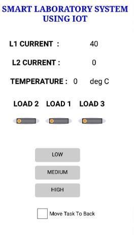
Fig. 5.1 Display of Smart Laboratory system Application
The icon which is pressed by the users is sent to Arduino Uno board through NodeMCU. According to the users commands Arduino Uno sends signals to relays to turn on or off the loads, thus the loads are controlled.Here the bulb is connected as a load.
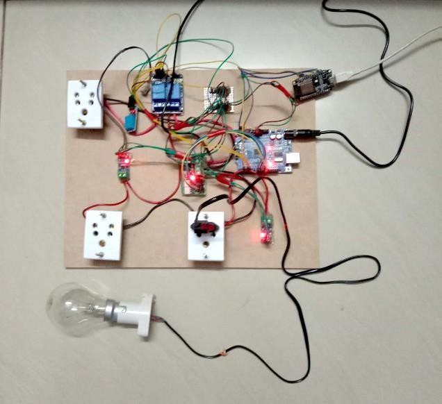
Fig 5.2 Smart Laboratory System Experimental setup
The icon pressed by the users is sent to Arduino Uno board through NodeMCU. According to the users commands Arduino Uno sends signals to relays to turn on or off thus the loads are controlled. The intensity of light can be controlled through high, medium and low icons.
When user clicks on high icon in app sends data to Arduino Uno through NodeMCU, Arduino sends to dimmer module. Dimmer module accepts data in digital format. Arduino sends 0000 data to dimmer module. 0000 data in dimmer module indicates 100% so the light will get high intensity.

Fig 5.3 Output of bulb with High intensity
When user clicks on low icon in app sends data to Arduino Uno through NodeMCU, Arduino sends to dimmer module. Arduino sends 1000 data to dimmer module. 1000 data in dimmer module indicates 40% so the light will get high intensity.
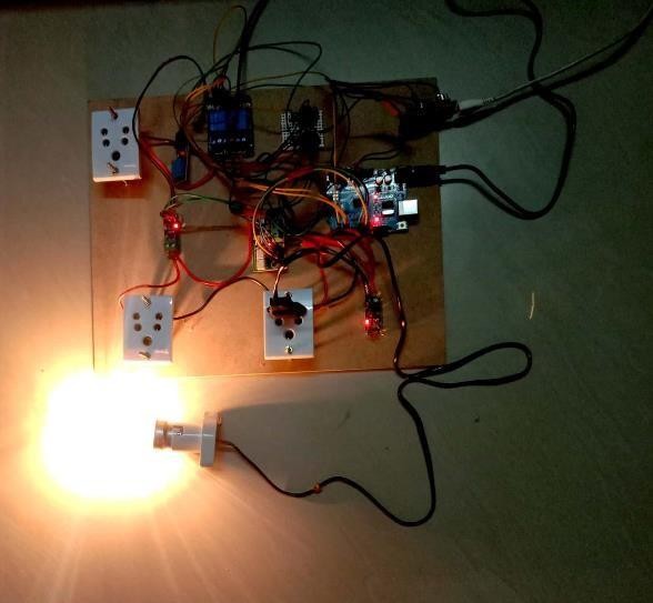
Fig 5.4 Output of bulb with Medium intensity
When user clicks on low icon in app sends data to Arduino Uno through NodeMCU, Arduino sends to dimmer module. Arduino sends 1101 data to dimmer module. 1101 data in dimmer module indicates 10% so the light will get high intensity.
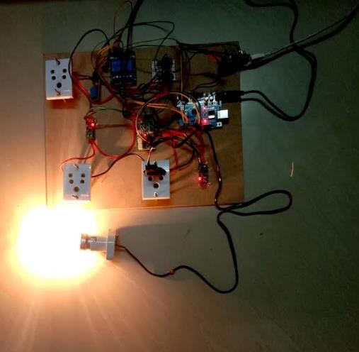
Fig 5.5 Output of bulb with Low intensity
Conclusion
The Smart Laboratory System using Internet of Things has been experimentally proven to work satisfactorily by connecting simple appliances to it and the appliances were successfully controlled remotely through internet. In this work, the proposed system facilitates the users to control the appliances such as lights, fans, projector and pc’s just by giving commands through app. Thus all devices can be controlled universally, and the status of the devices can be visualized. The current consumed by the devices can be known and the temperature of the room is displayed. This feature will help the user to analyze the status of these devices anytime and anywhere. It reduces human intervention in monitoring the devices.
References
[1] Deepali Javale, Mohd. Mohsin, Shreerang Nandanwar “LAB Automation and Security System Using Android ADK” in International Journal of Electronics Communication and Computer Technology (IJECCT) Volume 3 Issue 2 March 2013 [2] Javale, D., Mohsin, M., Nandanwar, S. and Shingate M. 2013, “Home automation and security system using Android ADK”, International journal of electronics communication and computer technology (IJECCT), vol.3, issue 2, pp.382-385. [3] M. Poongothai, A.L Karupaiya, R.Priyadarshini “ Implementation of IoT based Smart Laboratory” [4] P. Muthu Subramanian, A.Rajeswari. M.Poongothai “Design and implementation of iot based smart laboratory” [5] S.P.Pande, Prof.Pravin Sen, “Review On: LAB Automation System For Disabled People Using BCI” in IOSR Journal of Computer Science (IOSR-JCE) e-ISSN: 2278-0661, pISSN: 2278-8727 PP 76-80 [6] Sirsath N. S, Dhole P. S, Mohire N. P, Naik S. C & Ratnaparkhi N.S Department of Computer Engineering, 44, Vidyanagari, Parvati, Pune-411009, India University of Pune, “LAB Automation using Cloud Network and Mobile Devices” [7] Supriya Sonar, MayuriMujmule, Tejashwini Mangalgire, Prof. Thawali.B.R . 2016 “Home Automation using IoT”, International Journal of Engineering and Computer Science,vol6,issue 4,pp. 20923-20926 [8] Prof. V. P. Kaduskar, Nitish Gupta, Yash Bhardwaj, Shivam Kumar IoT BASED LAB AUTOMATION SYSTEM
Copyright
Copyright © 2024 P. Roopa Ranjani. This is an open access article distributed under the Creative Commons Attribution License, which permits unrestricted use, distribution, and reproduction in any medium, provided the original work is properly cited.

Download Paper
Paper Id : IJRASET65469
Publish Date : 2024-11-23
ISSN : 2321-9653
Publisher Name : IJRASET
DOI Link : Click Here
 Submit Paper Online

