Ijraset Journal For Research in Applied Science and Engineering Technology
- Home / Ijraset
- On This Page
- Abstract
- Introduction
- Conclusion
- References
- Copyright
Comparison of Stability Analysis of Building by Euro and Indian Code
Authors: Dipanshu Jakhar
DOI Link: https://doi.org/10.22214/ijraset.2024.63300
Certificate: View Certificate
Abstract
Precast concrete construction is a construction in which the concrete is cast in molds as per the requirement, treated in a controlled factory environment, and then transported to the construction site and put in the desired place. Therefore, in this report the comparison of stability analysis of building by euro and Indian code is been carried out. The methodology used for manual calculation of stability check is calculation of wind analysis and mass load analysis where firstly, the horizontal load coming on the structure is calculated. The horizontal load includes the wind load and mass load. The critical direction of both loads is determined and then applied at floor levels along with the geometrical imperfection load. Second is based on the relative stiffness of each Stability wall, the floor loads are distributed among the stability walls at each floor level. And finally, the local stability of each wall is checked. The stability checks for local stability are- • Overturning check. • Sliding check. All the analysis and design are done as per Euro-codes and Indian code. So that at the end the comparison of both can be carried out. After the same the study finds out that the design of structure from European code is much safer than Indian code because the study reveals the in European Code, they take more factor of safety into consideration such as mass load is used for low seismic zone whereas in Indian code there is no such parameter.
Introduction
I. INTRODUCTION
A. Introduction of Building
Sneakerhaven is a residential structure located in Denmark. It is a 4 Story structure and has a basement as well. It contains two blocks A and C and has a common basement. The dimensions of the Structure are Length =62m, Width =9.8m, and height =12.5m including a parapet of 0.5m. It is a complete Pre-Cast Concrete structure and, in this study, a full detailed Stability Analysis is carried out by using different codes i.e., Euro Code and Indian Code to compare the stability from both the codes to know the differences. The Precast elements mainly include Walls (both interior and Exterior), Slabs, beams, staircase, and some other custom-made elements, etc. Precast elements are suitable to take the gravity loads, lateral loads (wind and mass load), and handling stresses and at the same time provide stability to the structure. A precast construction is just like placing and staking the play cards adjacent to each other and ensuring that it is globally and locally stable.
Structural stability is the most critical concern in the Pre-Cast Structure. That is the reason the possibility of progressive collapse should be taken care of i.e., if by any means any structural element fails it will result in the progressive collapse of the whole structure. Also, there should be proper interaction between the precast slab and the pre-cast walls to facilitate and promote the overall structural behavior and transfer of shear.
B. Objectives of the Study
- To know the structure stability of a sneadkerhaven building Denmark by manual calculation using European code and Indian code.
- Study and compare stability of structure from both the codes to attain with the differences between both codes.
C. Scope of the Study
The scope of this paper is to find out and compare the stability analysis of building using European code and Indian code and adopt methodology of wind analysis and mass load analysis for the calculation of manual stability analysis of the building to know what the difference in using different codes is.
II. LITERATURE REVIEW
To attain the objectives of the study, there is need to have an idea of the findings and methodology adopted earlier period was felt desirable. The review of literature of comparison of stability analysis could provide a framework for the present study and serve as a point of departure for further pragmatic investigation. Findings of the existing literature are:
(Bhavsar*, 2014) In this research the researcher tries to compare EURO standards with Indian standards using structural software in R.C. buildings, where frames are considered as main structural elements, which resist shear, moment, and torsion effectively. These frames are subjected to variety of loads, where lateral loads are always predominant. Infrastructures of Gulf countries are always remarkable as they mostly follow EURO standards for construction development.
(Dr. S.V. Itti, 2015) In this report the researcher focuses on the comparison of the Indian Code (IS) and International Building Codes (IBC) in relation to the seismic design and analysis of Ordinary RC moment resisting frame (OMRF), Intermediate RC moment-resisting frame (IMRF) and Special RC moment-resting frame (SMRF). The analytical results of the model buildings are then compared and analyzed taking note of any significant differences. This study explores variations in the results obtained using the two codes, particularly design base shear, lateral loads, drifts, and area of steel for structural members for all RC buildings in both the codes. The discussion in this study will be confined to monolithically cast reinforced concrete buildings. Specific provisions for design of seismic resistant reinforced members are presented in detail. Provisions of Indian and International Buildings Codes are identified. Target deflection of the building is achieved at a lower lateral force in SMRF IBC i.e., the concept of lesser force and more deflection is followed. However, in OMRF, IMRF and SMRF of Indian Code lateral force applied in higher as a result the deflection on the top of the building exceeds the target deflection? To keep the deflection within the permissible limits we then increase the column and beam sizes to make the building stiffer and maintain deflection within the permissible limits. This work aims at the comparison of various provisions for earthquake analysis as given in building codes of Indian Code and International Building Codes.
(Nourhan Sayed Fouad, 2017) In this the researcher talks about that the structural design of the building includes the calculation of the applied wind loads as one of the major items in the design process. The available codes data for the listed structures in these codes extracted from wind tunnel experiments but not cover all the designed structures types. There is a necessity to provide the designer with design wind parameters considering that the experimental data is costly and not always available. This research aims to facilitate the necessary wind parameters for the structural design such as pressure distribution, drag coefficient for some building adopting the Computational Fluid Dynamics (CFD) techniques. The validation of the application of CFD technique with existing wind tunnel results for some structures is investigated. Then the application of the CFD techniques performed on some structures such as single span short gable structure with mono and double slopes, trusses, and domes. The basic parameters considered in the analysis of gable building including roof slops, wind direction. In addition, for gable buildings, the different roof zones coefficients of pressure assessed to compare the application of CFD technique with the international wind standards and codes of practice. The obtained results compared with each of the Euro code and ASCE10.
(Nandi, 2014) In this paper the researcher is intended to compare the design of reinforced concrete structure with various international codes from economical point of view. Three different famous structural building codes have been adopted. These are the IS456:2000, BS8110:1985, and Euro Code2:1992. These codes have been compared in the strength design requirements of structural elements. The comparison includes shear design. Throughout this study elaborated design models and criteria of the considered codes have been exhibited. Although the principles contained in these codes are basically the same, they differ in details.
(Roy1, A Comparative Study of International Structural Building Codes , 2020) In this the researcher attempts to exhibit a comparative study for the design of reinforced concrete structures. In this research, two International structural codes have been used to analyze the different processes of strength designs, which are, IS456:2000 and Euro Code2:1992. This study elaborates the criteria of codes and exhibits the design of structures. However, the principles in these codes are the same but are different in its details. This project intends to relate IS 456-2007 and Euro code II. The broad design standards (L/D ratio, stress-strain block parameters, load combinations and the formula compared along with the area of steel) for vital structural members to get an overview of how the codes illustrate in correspondence to each other. Emphasis will be put to the results in a tabular and graphical description for greater clarity and parallel interpretation.
(Tejaswini M L, 2018) In this research paper talks about that reinforced concrete frames are the most used method of construction in India. With the economic growth, the unavailability of urbanization and horizontal space has increased the cost of land and the demand for agricultural land. High-rise buildings are more popular in Indian architectural scenes, especially in cities. For high-rise buildings, not only must the building bear a gravity load, but it must also withstand lateral forces. Many important Indian cities are high-risk seismic belts. Therefore, strengthening the lateral force construction is a prerequisite in this study the aim is to analyze the response of a high-rise structure to lateral loads using static and dynamic seismic loads and static wind loads. This analysis procedure is based on IS codes for Design analysis of Structures. The results of analysis are used to verify the structure fitness for use, finally the comparison of all lateral stability checks has been carried for zone 2 and zone 3.
(MD. MAHBOOB RAHMANI1, 2021) In the research paper the researcher talks about modern residential structure which is going higher and higher these days. The impact of lateral loads in the form of wind/Earthquakes affects the performance of these structures dramatically. It is often a practice among structural engineers to use shear walls in place of columns. However, the shear walls do help a lot in resisting the lateral shear but it is often the reason for making the structure unnecessarily stiff. While columns do improve the ductility of a structure but they are often not capable of resisting the entire shear. Thus, it becomes necessary to decide the right proportion of shear walls and columns to be used for structures of particular height. Here an attempt had been made to investigate the seismic performance of different regular and irregular structures of varying height with shear walls by using ETAB software. Computer models have been analyzed and base line parameters have been decided. Numerical/ analytical studies have been carried out to investigate the impact of these base line parameters on our problem. Finally, regression analysis has been carried out to understand the impact of the base line parameter. Here an attempt has been made to study the behavior of different structures of reinforced concrete with different heights with and without shear walls. Coupled shear walls have also been studied to understand the comparative merit or demerit of framed structures with shear wall structures. Studies have been carried out on sample model structures and analysis has been carried out by ETABS software. It has been ensured to consider sample models that represent the current practices in structural design to include different structural configurations. Models having varied structural configurations like framed, shear wall, core in core etc. have been taken into consideration. The inherent asymmetry present in the structures has also been dealt. The results have been tabulated and plotted to study their comparative behavior and interaction with each other. The findings of the study have been summarized and discussed.
(Singh1, 2015) In this research paper the researcher attempts to design of Water Tanks is subjected to Dead Load + Live Load and Wind Load or Seismic Load as per IS codes of Practices. Most of the times tanks are designed for Wind Forces and not even checked for Earthquake Load assuming that the tanks will be safe under seismic forces once designed for wind forces. In this study Wind Forces and Seismic Forces acting on an Intze type Water tank for Indian conditions are studied. The effect of wind on the elevated structures is of prime importance as Wind flows relative to the surface of ground and generates loads on the structures standing on ground. Most of the designers consider the wind effect and neglect the seismic effect on the structure. The Indian Standard Code IS 875(Part-3) 2003 and IS 1893-2000 for Wind & Seismic effect is used in this study. The Elevated Structure is designed for various Wind forces i.e. 39 m/s, 44 m/s, 47 m/s & 50 m/s and the same is cross checked with different Seismic Zones i.e. Zone-II, Zone-III, Zone-IV, & Zone-V by ‘Response Spectrum Method’ and the maximum governing condition from both the forces is further used for design & analysis of staging. It is found from the analysis that the Total load, Total moments, and Reinforcement in staging i.e. Columns, Braces & also for Raft foundation varies for Case-1, Case-2, Case-3 & Case-4.
(B.N1, 2014) In this research paper the researcher talks about the high-rise buildings require high frame structure stability for safety and design purposes. This research focused on P-delta analysis to be compared with linear static analysis. In this study, an 18-story steel frame structure with 68.9 m has been selected to be idealized as multi story steel building model. The model is analyzed by using STAAD.Pro 2007 structural analysis software with the consideration of P-delta effect. At the same time the influence of different bracing patterns has been investigated. For this reason, five types of bracing systems including X, V, Single Diagonal, Double X, K bracing with unbraced model of same configuration are modeled and analyzed. The framed structure is analyzed for Wind load as per IS 875 (part 3)-1987. After analysis, the comparative study is presented with respective to Maximum story displacement and Axial Force. The present work showed that the ‘X’ bracing in continuous bracing pattern is proved to be more effective with respect to both Static and P-delta analysis.
(HEHIR, 2005) In this report the researcher uses the methods used for stability calculations of columns, solid shear walls, pierced shear walls, coupled and uncoupled components, cores, single story structures and multi-story structures have been examined. The examination performed to ascertain short comings or advantages for different stabilizing components and systems. Analyses were made of deflection and buckling combining bending and shear for columns, solid shear walls and pierced shear walls. Calculation methods for single and multi-story structures concerning deflection and buckling due to translation, rotation, or a combination of the two are analyzed and the results are compared with finite element analyses results. The importance of pure torsion is somewhat neglected in these methods and therefore a method was devised for including a components torsional resistance in the calculations. The calculation methods are computer assisted through the use of Mathlab, Mathcad and Excel. Comparisons of results are made between the calculation methods and Finite Element Analysis performed with a programmed called SOLVIA. Vianello’s method for calculating critical buckling loads, of columns and solid shear walls, due to bending has proven its worthiness. The method for calculating stability of pierced shear walls, according to studied, has proven itself to be in need of improvements. The use of the polar moment of inertia has proven to give inaccurate results. The result comparison of the single-story structures concerning translation, rotation and combined rotation and translation show that the calculation methods are satisfactory. Concerning multi story structures subjected to translation or rotation a question arose concerning the interaction between the stabilizing components and the floor slabs. The inclusion of a central cores owns torsional resistance into the calculation methods led to improved results. The results showed that further investigation of the calculation methods concerning stability of tall buildings is advisable and that specifically methods for determining the interactive behavior of stabilizing systems joined by floor slabs should be researched.
(a F. C., 2016) In this research paper the researcher talks about the moment in which civil engineering is undergoing a phase where structural projects have been developed with structural systems composed of different and complex elements, some methods and criteria are used for the purpose of evaluating important aspects with regard to global and local stability. Among them, it is necessary to mention the parameters of instability α and γz. In this sense, this work has the objective to present the basic concepts of the instability parameters α and γz in accordance with what is clearly defined in the Brazilian standard ABNT NBR 6118; to present the results of simulations of models in the Brazilian structural software TQS varying the stress of compression in the columns in order to relate these values with the stability parameters.
(Alexander M. Belostotskya, 2016) In this research paper the researcher talks about the strength and stability analysis of load bearing structures of Evolution Tower (high-rise 54- story building) with allowance for actual positions of reinforced concrete structural members (columns and walls). Finite element method (FEM) is used for structural analysis. The authors present formulations of problems, governing equations, information about basic three-dimensional finite element models (so-called “design” (ideal) model, the first “actual” model (taking into account the deviations of positions of columns from the project) and the second “actual” model (taking into account the deviations of positions of walls from the project)) of the coupled system “Evolution Tower – foundation” within ANSYS Mechanical software and their verification, numerical approach to structural analysis and corresponding solvers. Finite element models include mainly 4-node structural shell elements (suitable for analyzing foundation slabs, floor slabs and load-bearing walls) and three dimensional 2-node beam elements (suitable for analyzing beams and columns), special spring-damper elements and multipoint constraint elements. Detailed finite element mesh on the bottom foundation slab is agreed with the location of piles. The advanced model of professor y.u. zaretsky is used for approximation of soil behavior. Construction sequence and various types of nonlinearities are taken into account. The results of modal analysis, static and dynamic analysis with various load combinations (gravity load, façade load, dead (constant) loads, temporary loads, wind load, snow load, crown load etc.) are considered, the results of the regulatory assessment of the strength of structures (obtained with the use of corresponding software in accordance with design codes of the Russian Federation) are under consideration as well. The corresponding displacements, stresses, natural vibration frequencies can be used for research and development of the correct monitoring method of the foundation and load-bearing structures of a high-rise building.
III. RESEARCH METHODOLOGY
After going through above literature, the researcher found that nowadays different countries use their codel provision to make their structure like- International building code, Indian code, Euro code etc. And it was also found that there is no study has been done so far which tells about the difference in the results of these codes. So, this study has been conducted to know the difference. For which we have taken a building in which we will do manual stability analysis by applying both Euro code and Indian code and see the difference between both the result. The study was undertaken to understand the stability of structure by doing a comparative analysis of a building using Euro code and Indian code to know whether the structure is stable from both the codes or not and what new can be found from this study. For this purpose, the below methodology has been used.
A. Method for Data Collection
For the achievement of the objectives of the study, data was collected through secondary source i.e., the company which has made this building (Ramboll company).
B. Step by Step Procedure in Order to Calculate Stability
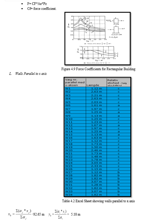
- Selection of Stability Walls
For analysis we take only those walls as Stability walls (that take the lateral loads from floor slabs and transfer it to the foundation) that are continuous from the top to bottom of the building and they should also not have any openings (due to doors, windows, etc.) when seen in elevation. Other walls with openings also contribute to load transfer but for the time being we ignore them to be on the safer side and assume only the walls that are continuous take the load. Also, the length of the wall should not be less than 1 m.
2. Codes used in the Study
- BS EN 1990 Basis of Design.
- BS EN 1991 1-4 Wind action on Structures.
- BS EN 1992 Design of Concrete Structures.
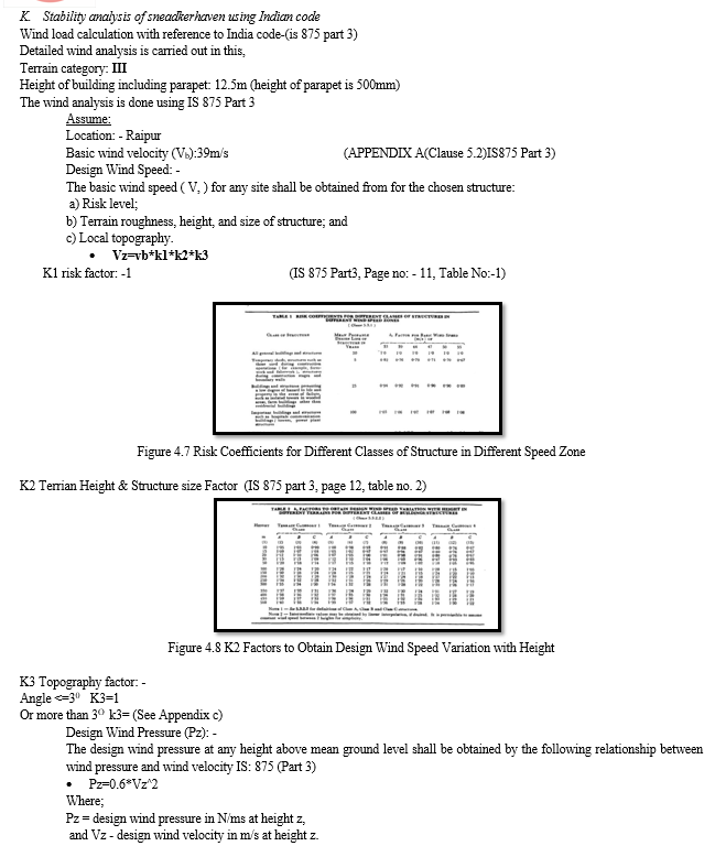
- IS 875 PART 3 code of practice for design loads.
- IS 875 PART 1 criteria for earthquake resistant design of structures: general provision and buildings.
- IS 456 2002 code for practice for plain and Reinforced concrete.
3. Load Calculation
- Wind Load
Wind load is the Load that comes on the structure when the wind blows around the building. The Wind load becomes more critical as the height of the building increases. The magnitude of the wind load on the structure depends on number of quantities like Terrain height, orographic factor, roughness factor, percentage of openings in the structure, topography etc. The total wind load acting on the structure can be calculated using EN-1991-(1-4) and IS 875 PART 3.
- Mass Load
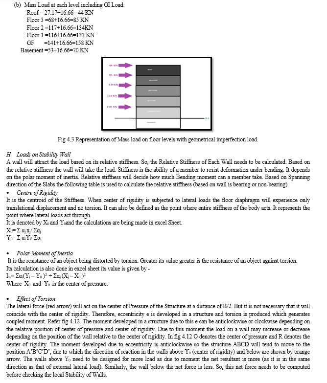
Mass Load is the total load of the building. It included both Dead load and Mass Load. It is calculated by measuring the area/length of the elements (like walls, slabs etc.) from Revit model and multiplying by the unit weight from the Design Basis. Like the Wind load Mass load is also a lateral load and acts at each floor level. The magnitude of Mass load is Same in both directions as Mass of a body is a constant quantity.
- Imperfection Load
The geometrical imperfection load in a structure is represented by inclination. This load is generated in a structure due to error in geometry during construction. it accounts for unfavorable effects of possible deviations in the geometry of the structure and the position of loads shall be taken into account in the analysis of members and structures. These loads are taken into account in ultimate limit state and are not considered in serviceability limit state. This Load is calculated and distributed among floors equally in both directions (along and across the building).
4. Relative Stiffness
A wall will attract the load based on its relative stiffness. So, the Relative Stiffness of Each Wall needs to be calculated. Based on the relative stiffness the wall will take the load. Stiffness is the ability of a member to resist deformation under bending. It depends on the polar moment of inertia. Relative stiffness will decide how much Bending moment can a member take. The load is distributed in all the walls as per their relative stiffness i.e. more the stiffness more loads the wall takes.
5. Polar Moment of Inertia
It is the resistance of an object being distorted by torsion. Greater its value greater is the resistance of an object against torsion.
its value is given by-
Iw= ?αi(Yi – Y0 )2 + ?αj (Xj – X0 )2
Where X0 and Y0 is the center of pressure.
6. Stability Check
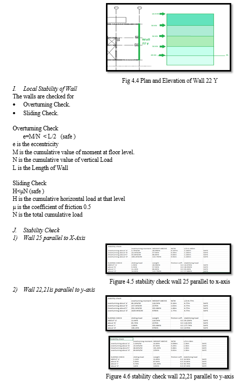
The walls are checked for
a. Overturning Check
- e=M/N < L/2 (safe)
e is the eccentricity
M is the cumulative value of moment at floor level.
N is the cumulative value of vertical Load
L is the Length of Wall
b. Sliding Check
- H<μN (safe)
H is the cumulative horizontal load at that level
μ is the coefficient of friction 0.5
N is the total cumulative load
IV. STRUCTURE STABILITY EURO CODE - SELECTION OF STABILITY WALL
The first step in the Stability analysis is the selection of the stability walls. For analysis we take only those walls as Stability walls (that take the lateral loads from floor slabs and transfer it to the foundation) that are continuous from the top to bottom of the building and they should also not have any openings (due to doors, windows, etc.) when seen in elevation. Other walls with openings also contribute to load transfer but for the time being we ignore them to be on the safer side and assume only the walls that are continuous take the load. Also, the length of the wall should not be less than 1 m. Discontinuous walls are not taken as stability wall because at opening there is usually beam column action and high stress concentration.
Revit software is used to check which walls are continuous so as to take them as stability wall. Sections are cut at various walls in Revit models and seen in elevation to check which walls is continuous Fig 4.3 which shows how walls are selected. The orange color shows the stability walls. Note that there are no windows, doors in between the walls therefore, walls are numbered with subscript x and y to show which walls are along and across the buildings. Also, the length of each wall is noted.
A. Wind Load
In precast concrete Structures the loads to be carried are vertical loads and Horizontal/Lateral loads.
In Denmark there is rarely any seismic activity, so the dominant lateral loads are the wind Loads. As there is very low seismicity, they take another load into consideration called The Mass Loads.
Both the wind and the Mass loads act at floor levels in both directions but we are more concerned with the direction in which the loads will be critical.
Wind load is the Load that comes on the structure when the wind blows around the building. The Wind load becomes more critical as the height of the building increases. The magnitude of the wind load on the structure depends on number of quantities like Terrain height, orographic factor, roughness factor, percentage of openings in the structure, topography etc. The total wind load acting on the structure can be calculated using EN-1991-(1-4). The detailed wind analysis of the structure in consideration (Snedkerhaven) is carried out in section 4.6 in detail.
As wind load is an area load therefore it is obvious that the wind load will be critical in the direction across the building, because more area is along this direction. Also, one thing to be noted here is that as Mass load is the Mass of the building so unlike wind load it is same in both directions.
B. Mass load
Mass Load is the total load of the building. It included both Dead load and Mass Load. It is calculated by measuring the area/length of the elements (like walls, slabs etc.) from Revit model and multiplying by the unit weight from the Design Basis. Like the Wind load Mass load is also a lateral load and acts at each floor level. The magnitude of Mass load is same in both directions as Mass of a body is a constant quantity.
C. Load Path for Lateral Loads
The lateral loads be it wind or mass acts on the floor diaphragm. Floor diaphragm carries half of the lateral load that acts on the floor above it and half below it. So, the load is transferred from the floor diaphragms to the stability walls that transfer it to the ground / foundation. The amount of load that a wall attracts depends on its relative Stiffness. In the figure below fig 3.6 shows the load path that the lateral loads take to reach the foundation.
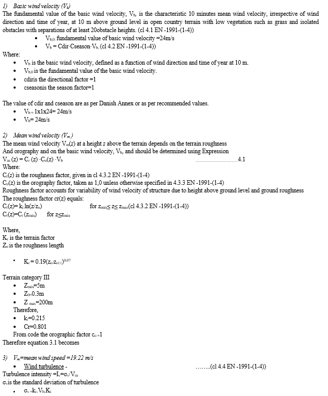
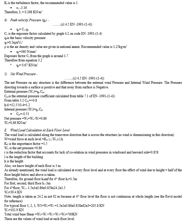
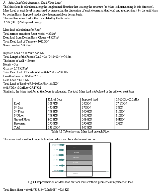
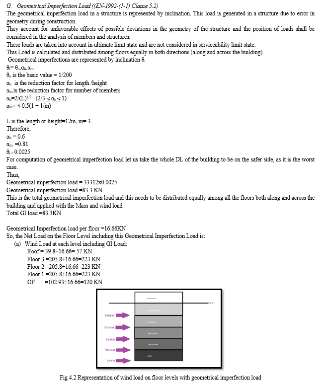
D. Wind load calculation for sneadkerhaven
Detailed wind analysis is carried out in this section.
Terrain category: III
Height of building including parapet: 12.5m (height of parapet is 500mm)
The wind analysis is done using EN -1991-(1-4)
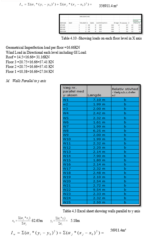
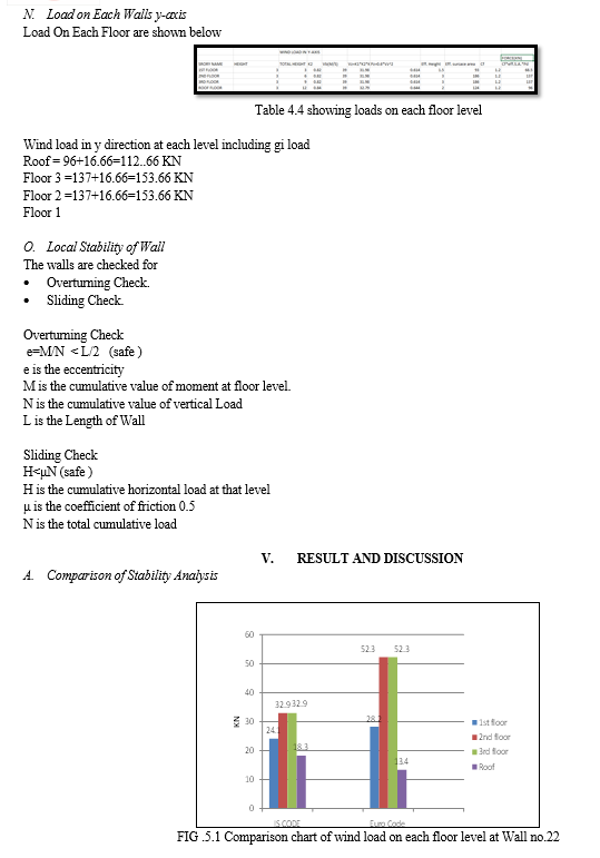
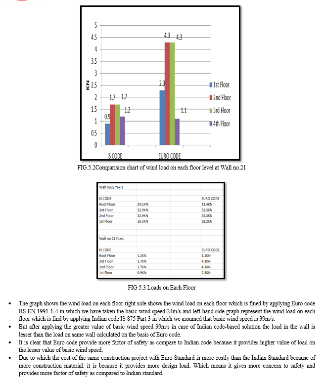

Conclusion
A. Conclusion In this study of comparison of stability analysis of SNEADKERHAVEN building. The stability of the structure is found out by using different code i.e., Euro code and Indian code where the researcher calculate the stability of structure by manual method using wind analysis for this study the data is taken from the Ramboll company Gurgaon. The results of the comparative study led to the following conclusions- 1) In European Code we used basic wind velocity 24m/s where we get and in comparison, to Indian code we used basic wind velocity 39m/s where we get. Therefore, we found that even after taking less wind velocity in case of European code it provides high wind load in comparison to Indian code where the wind velocity is higher but still the wind load is low. Which clearly shows that European code use more factor of safety into consideration while designing of structure that is why it can bear more loads. 2) From the above study of manual calculation of stability analysis of sneadkerhaven building it has concluded that building is stable in all the aspect and can resist all the loads which occur in its life span studied from both euro code and Indian code. 3) More factors are considered for stability analysis in Euro code as compared to Indian code such as mass load which is taken into consideration while doing calculation in euro code for low seismic zone while on other side of Indian code there are no such parameters. 4) It also been personally observed that calculation from European code is much more complex than Indian code because it contains more specific terms which makes its complex but despite it make euro code more accurate and more practical. B. Suggestion 1) Both the codes are good at their level but there are certain parameters which taken into consideration in European code but not on Indian code. Therefore, if not using Euro code we must take certain parameter of euro code into consideration for safety of structure example like mass load for low seismic zone. 2) Euro code must be use for big project like construction of dams, highways, railways etc. as they have long life span and required a high level of safety.
References
[1] a, F. C. (2016). Global stability analysis of structures and actions to contol their effects. Brazil: IBRACON Structures and Materials Journal . [2] a, T. r. (2018). COMPARATIVE STUDY OF ZONE 2 AND ZONE 3 FOR EQUIVALENT . Banglore: International Research Journal of Engineering and Technology (IRJET). [3] Alexander M. Belostotskya, b. P. (2016). Strength and stability analysis of load-bearing structures . Russia: Elseiver B v. [4] B.N1, M. (2014). STABILITY ANALYSIS OF STEEL FRAME STRUCTURES: P-DELTA . Karnataka: International Journal of Research in Engineering and Technology . [5] Bhatt, P. (2011). Prestressed concrete desgin to Eurocodes hardcover. uk: Taylor & Francis Ltd. [6] Bhavsar*, A. P. (2014). Comparative study of typical R.C. building using . surat: International Journal of Scientific and Research Publication. [7] Dr. S.V. Itti, P. A. (2015). A Comparative Study on Seismic Provisions Made in Indian and. karnataka: Academic Edu. [8] HEHIR, D. G. (2005). Stability of Tall Buildings. sweden: Chalmers University of Technology. [9] Jain`, A. (2012). Reinforced CXoncrete - Limit State Desgin (7 ed.). Delho: Laxmi Publication. [10] Kirkitadzea, M. (2008). Adjuvanted vaccine components: Analysis of structure and stability . Canada: Elesiver B.v. [11] MD. MAHBOOB RAHMANI1, M. D. (2021). COMPARATIVE ANALYSIS OF REGULAR AND IRREGULAR BUILDINGS WITH . Farifdabad: International Research Journal of Engineering and Technology. [12] Nandi, L. (2014). Design Comparison of Different Structural . Karnataka: International Journal of Engineering Research & Technology. [13] Nourhan Sayed Fouad, G. H. (2017). Comparative study of international codes wind. Cario eqypt: Alexandria Engineering Journal. [14] Roy1, A. (2020). A Comparative Study of International Structural Building Codes . west bengal: International Research Journal of Engineering and Technology. [15] Roy1, A. (2020). Comparative Study of International Structural Building Codes . west bengal: International Research Journal of Engineering and Technology (IRJET) . [16] Singh1, N. J. (2015). DESIGN ANALYSIS & COMPARSION OF INTZE TYPE WATER TANK . Maharshtra: International Journal of Research in Engineering and Technology . [17] Standard, B. o. (2000). IS 456:2000 Indian Standard code oractice for plain & Reinforced concrete (Vol. 4). new delhi: Bueau of Indian Stanard. [18] Tejaswini M L, S. N. (2018). COMPARATIVE STUDY OF ZONE 2 AND ZONE 3 FOR EQUIVALENT . Banglore: International Research Journal of Engineering and Technology . [19] Trevor Draycott, P. B. (2009). Structural Elements Desgin Manual: working with Eurocode. UK: Taylor & Francis Group.
Copyright
Copyright © 2024 Dipanshu Jakhar. This is an open access article distributed under the Creative Commons Attribution License, which permits unrestricted use, distribution, and reproduction in any medium, provided the original work is properly cited.

Download Paper
Paper Id : IJRASET63300
Publish Date : 2024-06-15
ISSN : 2321-9653
Publisher Name : IJRASET
DOI Link : Click Here
 Submit Paper Online

