Ijraset Journal For Research in Applied Science and Engineering Technology
- Home / Ijraset
- On This Page
- Abstract
- Introduction
- Conclusion
- References
- Copyright
Steady State Thermal Analysis of Cylinder Fins with Varied Materials and Thicknesses
Authors: Shadab Khan, Dr. B. K. Chourasia
DOI Link: https://doi.org/10.22214/ijraset.2023.54771
Certificate: View Certificate
Abstract
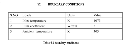
In automobiles, the engine cylinder is subjected to large temperature variations and thermal stresses. The engine cylinder has fins installed on it to increase heat transfer and cool the engine cylinder. By doing a thermal study on the fins, you can figure out how quickly heat is transferred inside the engine cylinder. The engine cylinder is one of the crucial components of an automobile and is vulnerable to large thermal stresses and abrupt temperature fluctuations. In an effort to cool the cylinder, fins are positioned on its surface to accelerate heat transfer. A thermal analysis of the cylinder fins may be used to determine how much heat is lost inside the engine cylinder. The project\'s primary goal is to investigate how different cylinder fin shapes, materials, and thicknesses affect their thermal behavior. In this project 2mm, 2.5mm, 3mm thickness of fins are measured for rectangular fin geometry and circular fin geometry and these model are design by using CatiaV5. The steady state thermal analysis can be done by using ANSYS WORKBENCH .18. In this project we have taken four materials aluminum, aluminum alloy, cast iron, magnesium alloy. The geometries circular, rectangular fin design with these materials. These four materials are compared with different thickness of fin 2mm, 2.5mm, 3mm on the basis of heat flux and temperature distribution
Introduction
I. INTRODUCTION
We are known that the combustion of air and fuel inside the engine cylinder results in the production of hot gases by internal combustion engines. The temperature of the gases will be between 2300 and 2500 °C. This is a very high temperature that might burn the oil layer between the moving parts, increasing the danger of piston seizure and possibly harming piston rings, compression rings, oil rings, and other components.
The moving parts could then seize or weld together as a result of this. The cylinder material can also be harmed by high temperatures. As a result, this temperature must be lowered to between 150 and 200°C, where the engine will operate most effectively. Additionally undesirable is excessive cooling since it lowers thermal efficiency.
Fins are regularly used on cylinder blocks to increase heat dissipation. The cylinder block's outside is covered in fins, which are small, evenly spaced protrusion. The block may make greater contact with the surrounding air because of the increased surface area provided by these fins. As a result, heat from the engine is more efficiently transferred to the fins, where it is eventually discharged into the environment by convection. Cylinder blocks with fins help manage the operating temperature of the engine to increase performance and durability. By effectively distributing heat, the fins assist in minimising overheating, which may cause engine damage or reduced performance. Cylinder blocks with fins are typically seen in air-cooled engines found in motorcycles, small aircraft, lawnmowers, and certain vintage or specialty vehicles. Engines must have cylinder blocks with fins for efficient heat dissipation. The engine block's surface area is increased by the fins, allowing for improved cooling and preventing overheating issues, which improves overall engine performance and lengthens engine life
A. Natural Cooling System
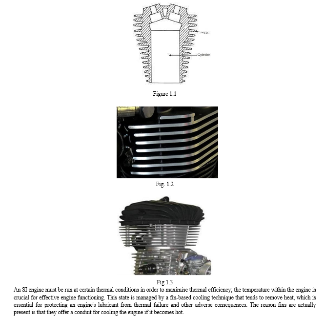
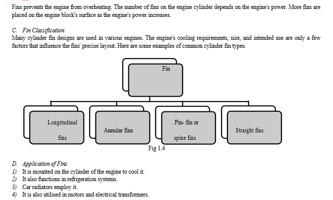
Larger engine components typically remain outside, exposed to the air around them. When the engines are running, the air impacts the engine and removes heat at a given relative velocity. Natural air-cooling is the term for this process since it uses natural convection to remove the heat from the air. The majority of the natural air is used to cool the engines of two-wheelers. There is a need to increase the engine's frontal cross-sectional area since heat dissipation depends on this region. An engine with a larger surface area will grow bulky, which will lower the power to weight ratio. Therefore, as a substitute design, fins are created to increase the engine's frontal cross-sectional area. Sharp protrusions called fins (or ribs) are present on the cylinder block and cylinder head's surfaces. They expand the cylinder's exterior region of contact with the air.
B. Fins
A fin is an extended surface designed to increase convection and, as a result, the rate at which heat is transferred to or from the environment. The rates of conduction, convection, and radiation determine how much heat an object transmits. Heat transmission is accelerated by increases in the convective heat transfer coefficient, the temperature difference between the object and its surroundings, or the object's surface area. Sometimes changing the first two alternatives is neither practical or economically viable. But increasing the surface area of the item by adding a fin might occasionally be a cost-effective way to solve heat transmission issues surface of the cylinder block. These are common for small motors and applications where space is limited. Straight fins increase surface area and ensure efficient cooling by promoting airflow between the fins
II. LITERATURE REVIEW
S .Selvaprakash Giri, K. Sivaramakrishnan, A. Sunil Kumar, G. Ramakrishna (2018) In order to achieve a better rate of cooling, the primary goal of this article is to explore the thermal dissipation of heat from the engine fin. By altering the geometry and using various materials, this may be studied. This study uses circular, rectangular, helical, tapered, longitudinal, and angular geometry. Grey cast iron and Aluminum Alloy 6061 are the materials employed in this analysis. Creo 3.0 is used to develop the design, while Ansys Workbench 16.1 is used to do the thermal analysis. According to our investigation, aluminum alloy 6061 exhibits the greatest thermal dissipation and the fastest rate of cooling, with round fins having the greatest value.
G.V. Subhash, B.N. Malleswara Rao, N. Srinivasa Rao, K. Ashok Kumar (2016)-The project's primary goal is to investigate how different cylinder fin designs, materials, and thicknesses affect how they conduct heat. In this project, different fin shapes with fin thicknesses of 2.5 mm and 3 mm are taken into consideration. The fins were created using AUTO CAD 2016.ANSYS WORKBENCH is used to do thermal analysis on the fins. Instead of the standard material, aluminium alloy 204, we used aluminium alloy 6063 and 7068 in our project. On the basis of overall rate of heat flux and efficacy, the geometries of circular, rectangular, and trapezoidal fins made of aluminum alloy 204, aluminum alloys 6063, and aluminum alloys 7068 of thicknesses 2.5 mm and 3 mm are compared. Aluminum alloy 6063 with a round shape and 2.5 mm thickness is discovered to have more.
Nalla Suresh, Mulukuntla Vidya Saga (2017)- The main objective of the project is to analyse the thermal characteristics of a roughly square cylinder model created in SOLIDWORKS-2013 and imported into ANSYS WORKBENCH-2016 for Transient Thermal analysis with an Average by varying the geometry (circular, rectangular), material (aluminum alloy, magnesium alloy), and fin thickness (3mm, 2mm).
One of the crucial components of an automobile that is regularly subjected to significant temperature swings and thermal stresses is the engine cylinder. Fins are positioned on the cylinder's surface to speed up heat transfer in order to cool the cylinder. It is possible to learn more about the temperature distribution and rate of heat dissipation inside the engine cylinder by performing a thermal research on the fins around the cylinder. Building an engine with such a big, complicated surface area is challenging given that we are aware that increasing surface area would accelerate the pace at which heat is wasted.
III. FINITE ELEMENTS METHOD
In order to address engineering and mathematics issues, the Finite Element Method (FEM) divides a complicated domain into smaller, more manageable subdomains known as finite elements. It is a potent numerical analytical technique that is widely utilised in numerous disciplines, including electromagnetics, fluid dynamics, structural analysis, and heat transfer, among others. The Finite Element Method's core idea is discretizing a complicated system into a finite number of components in order to approximate the behaviour of the system. Each element has a unique collection of features, including geometry, material characteristics, and boundary conditions, and is specified by a set of nodes. The values of the unknowns, such as displacements or temperatures, inside each element are then interpolated to estimate the behaviour of the system. The Finite Element Method has a number of benefits, including the capacity to deal with complicated geometries, adaptivity to improve the solution in regions of interest, and flexibility to incorporate various physics and boundary conditions. It is now a common tool for addressing a variety of engineering issues and has significantly advanced design, analysis, and optimization procedures across several sectors.
A. Ansys Program Includes following step
The software platform known as ANSYS Workbench was created by ANSYS Inc. and acts as a complete environment for engineering simulation and analysis. Engineers and designers can run complicated simulations across numerous disciplines because to its user-friendly interface and integration of several ANSYS simulation tools into a single framework.
- Workflow for Simulation: ANSYS Users that utilise Workbench may build up, administer, and analyse simulations in a single environment. It offers a graphical user interface for setting up simulation projects, organising them, defining input parameters, and visualising the outcomes.
- Geometry Modeling: Tools for geometry modelling are included in ANSYS Workbench, allowing users to import or generate 3D CAD models. It offers options for changing and simplifying geometry for simulation purposes and supports a variety of file types.
- Mesh: The programme has strong meshing capabilities to discretize the geometry into computational cells or finite elements. It consists of manual and automated meshing tools for regulating mesh quality and refinement.
- Pre- and post-processing tools are available in ANSYS Workbench for configuring simulation parameters, specifying boundary conditions, and tagging material characteristics. Additionally, it provides sophisticated post-processing features for plotting, graphing, animating, and reporting simulation results.
???????IV. MODEL DESCRIPTION
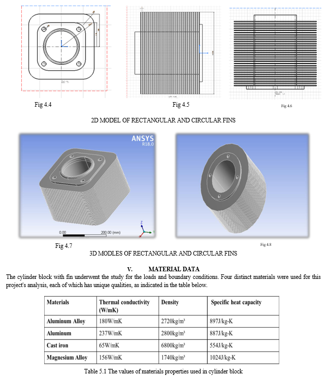
Fin and cylinder measurements were obtained from the standard dimensions. The usual proportions have undergone certain alterations in order to better suit our project. The fins' pitch, length, and thickness have all been altered. The dimensions for design are shown in the below. The Rectangular fins and circular fins are designs in catiav5 software using varying thickness of fin
All dimensions in mm
- Bore of cylinder:- 145mm
- Stroke length:- 225mm
- Length of fins:- 300
- Thickness of fins:- 2mm, 2.5mm, 3mm





 ???????
Conclusion
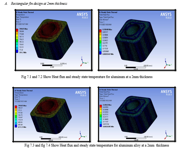
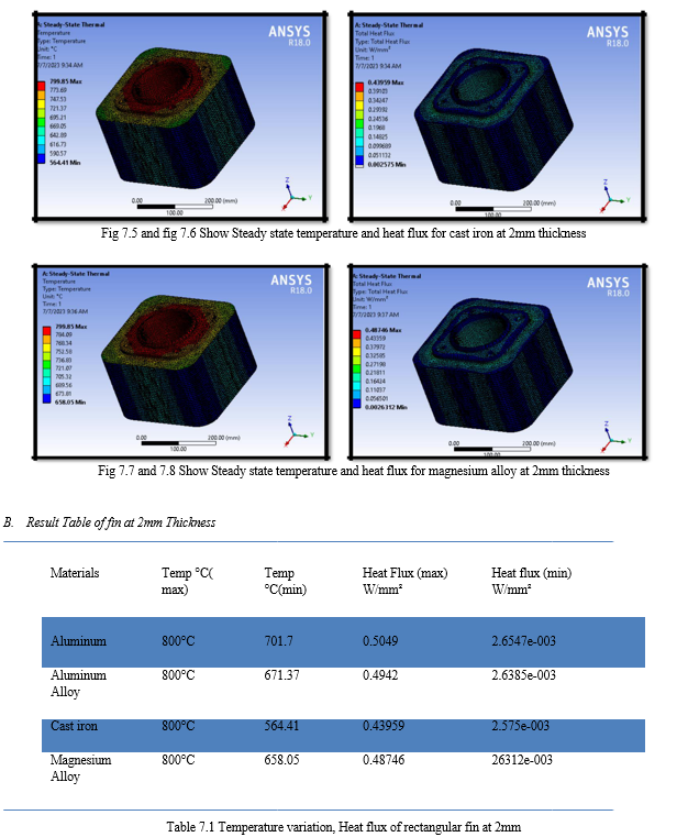
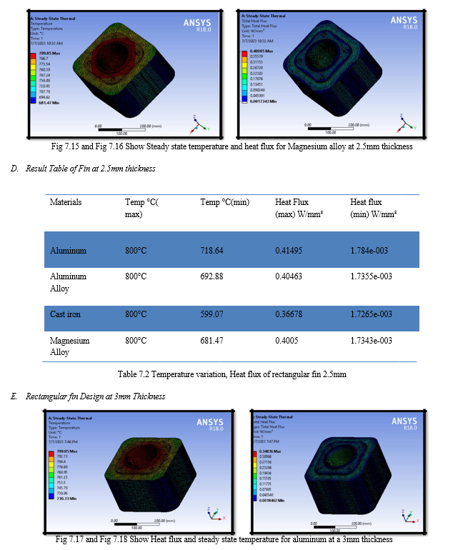
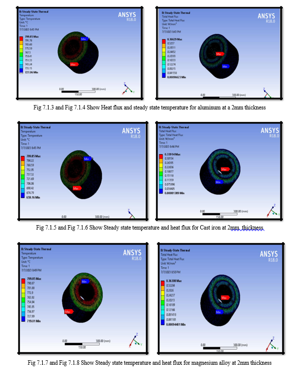
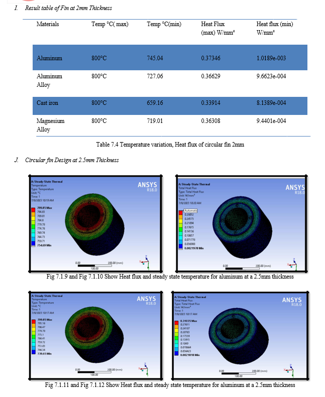
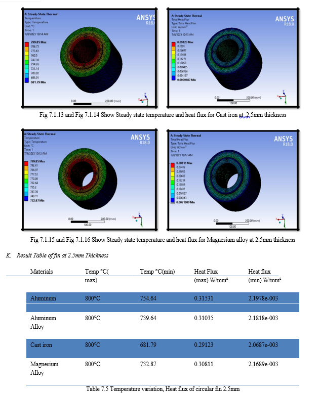
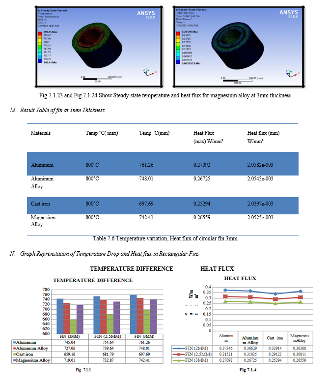
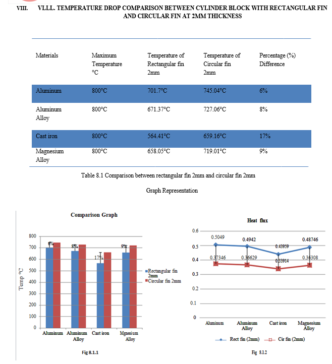
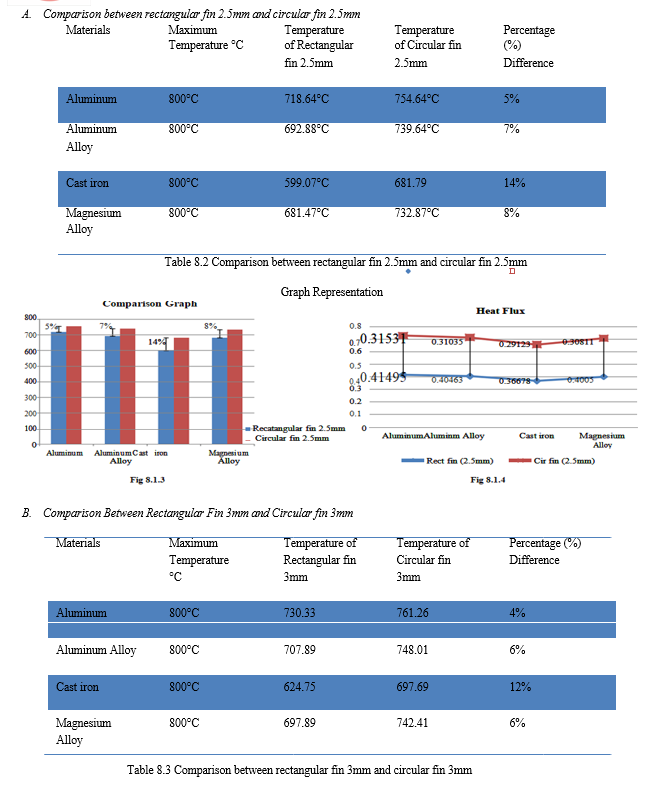
In the current study, analysis is carried out utilizing a cylinder model with added fins. This was loaded into the ANSYS workbench environment and the previously indicated boundary conditions were used. Fins of varied thicknesses and geometries, including circular and rectangular fins, are subjected to analysis. The outcomes are displayed below. This analysis can we done in steady state thermal analysis.The current study models a cylinder fin body using CATIA V5, and steady state thermal analysis is carried out using ANSYS Workbench 2018. These fins are a part of the engine\'s air cooling system. In the current study, we investigated four materials—Aluminum, Aluminum Alloy, Cast Iron, and Magnesium Alloy—as well as a number of other factors, including fin shape and thickness. By observing thermal analysis results we can clearly conclude that fin material cast iron for rectangular and circular gives the minimum temperature drop and in terms of heat flux the circular fin 2mm thickness is most effective. Now we have compared rectangular and circular fin those thickness 2mm. we have seen minimum temperature drop in rectangular fin and its difference from The circular fin 6% for aluminum 8% aluminum alloy 17% cast iron and 9% magnesium alloy . We have seen effective result for 2mm fin it give better air cooling system for comparing other.
References
[1] Heat and Mass Transfer, Second Edition, R. K. Rajput, S. Chand & Company Limited, New Delhi, 2002. [2] Heat and Mass Transfer by Ramachandran.S., Air Walk Publications, Chennai, 2003, Second Edition. [3] Mohan Lal Sharma, Sathpal Singh, and Mathew Abraham (17–19 December 1997) Impact of environmental factors on two-stroke SI engine performance, Proceedings of the XVth National Conference on IC Engines and Combustion, Vol.Internal Combustion Engines Fundamentals, Oxford & IBH Publishing Company, 1959, Paul W. Gill, James H. Smith, JR., and Eugene J. Ziurys. [4] Automobile Engineering Vol. II by Dr. Kirpal Singh, Standard Publishers Distributors, Delhi, 2004. [5] Heat Transfer from Finned Metal Cylinders in an Air Stream, A.E. Biermann and B. Pinkel, NACA Report No. 488 (1935). [6] Thermodynamic study of a combined heat and power system, Res.J. Recent Sci, 1(3), 76-79 (2012). Dev Nikhil, Attri Rajesh, Mittal Vijay, Kumar Sandeep, Mohit, Satyapal, and Kumar Pardeep. [7] Simulation and Experimental Evaluation of Air Cooling for Motorcycle Engine, TVS Motor Company Limited, Memon K. Zakirhusen, Sundararajan T., Indian Institute of Technology Madras, V. Lakshminarasimhan, Y.R. Babu, and Vinay Harne (2006). [8] Air-Cooling Effects of Fins on Motorcycle Engine, JSME International Journal, Series B, 49(3), (2006). Masao Yoshida, Soichi Ishihara, Yoshio Murakami, Kohei Nakashima, and Masago Yamamoto. [9] Internal and exterior fin heat transfer improvement approach for latent heat thermal energy storage in triplex tube heat exchangers is described by A. A. Al-Abidi, S. Mat, K. Sopian, M. Sulaiman, and A. T. Mohammad in Applied Thermal Engineering 53 (1) (2013) 147–156. [10] Zeng Wu Y, \"Finite Element Analysis for the Thermal Load of Piston in a Dimethyl Ether Fueled Diesel Engine,\" 2010 Wuhan International Conference on Mechanic Automation and Control Engineering (MACE), pp. 2895–2898. [11] (2009) D.G. Kumbhar et al. Convective Heat Transfer Augmentation from Horizontal Rectangular Fin by Triangular Perforations: Finite Element Analysis and Experimental Study. Proceedings of the International Conference on Mechanical Engineering Advances. [12] K. Mayilsamy and N. Nagarani (2010). The study is titled \"EXPERIMENTAL HEAT TRANSFER ANALYSIS ON ANNULAR CIRCULAR AND ELLIPTICAL FINS.\" 2(7):2839–2845 International Journal of Engineering Science and Technology.
Copyright
Copyright © 2023 Shadab Khan, Dr. B. K. Chourasia. This is an open access article distributed under the Creative Commons Attribution License, which permits unrestricted use, distribution, and reproduction in any medium, provided the original work is properly cited.

Download Paper
Paper Id : IJRASET54771
Publish Date : 2023-07-13
ISSN : 2321-9653
Publisher Name : IJRASET
DOI Link : Click Here
 Submit Paper Online

