Ijraset Journal For Research in Applied Science and Engineering Technology
- Home / Ijraset
- On This Page
- Abstract
- Introduction
- Conclusion
- References
- Copyright
Study on Tractive System and Power Conveyance of EV Go-Kart
Authors: B. Pavan Kalyan , B. Adithya, D. Sai Venkat Ruthviz, P. Nagesh, Dr. B. Vijaya Kumar
DOI Link: https://doi.org/10.22214/ijraset.2024.61036
Certificate: View Certificate
Abstract
This paper gives an overview on a cognizant strategy while selecting the major components of tractive system and power conveyance of Ev go-kart. This study was compiled according to the rules specified in the 2023-2024 GKDC. Go-Kart is a racing vehicle having very low ground clearance and can be worked on only flat racing circuits. The vehicle is iterative and is based on various engineering and reverse engineering processes depending upon the availability, cost and other such factors. All the parameters like Reliability, safety, Cost, Performance, aesthetics, ergonomics, Standard dimensions & material were also taken into consideration at the same time. We have also taken into account the battery management system, motors and other electrical management systems along with a brief description about their working and specifications. Through detailed analysis of the tractive system components such as motors, controllers, batteries, and drivetrain configurations, this research seeks to identify key parameters influencing the overall performance and acceleration characteristics of electric go-karts. Furthermore, the project evaluates the impact of various factors including motor selection, battery technology, and drivetrain layouts on the overall efficiency and dynamic response of electric go-karts. The findings of this study contribute valuable insights for enhancing the design and performance of electric go-karts, thus advancing the development of sustainable and high-performance recreational and competitive electric go-karts.
Introduction
I. INTRODUCTION
An electric go-kart is a type of go-kart powered by electric motors and batteries, as opposed to a traditional petrol engine. It is a vehicle specially designed for a flat track race. Go-kart structure refers to quadracycle vehicle that is used in sports and competition. Go-kart could also be called as the open-wheel car on land which could be made with or without the body-framework It has four harmonious wheels with the bottom, of which two of them assist for the turning of the vehicle with the control of steering and others would facilitate the transmit of the go-cart. Usually, the whole-body frame of the go-cart is made-up of steel pipes, apart from the other key components. There were some other parameters such as the types of materials used for the structure of the vehicle in-order to make it mechanically rugged and design of the chassis, these choices are very well concerned because they determine the safety of the vehicle and the structural analysis. now, due to the advancements in the technology and manufacturing materials go-carts are expected to be lighter, faster and should be more efficient in-terms of power consumption and overall performance as well.
Electric vehicles are gaining more and more popularity. Electromobility is becoming an everyday form of mobility, making life easier for the user thanks to the gradually introduced autonomy. Electrical vehicles are future of the world. Rather than using gasoline engine our aim is to design and develop Electric Go Cart vehicle by using high torque motors and batteries. It will be a single sitter cart whose chassis will be made from PVC Pipes. The main objective behind this project is to make an ecofriendly and more robust go cart vehicle. It has a simple design and economically affordable are the key features of our cart which has multiple applications like it can be used for Adventure purpose and Sports. Electric propulsion systems for competition racing karts have not yet reached the point in their development cycle whereby a recognised technical formula has been achieved for their introduction into sanctioned competitive electric kart racing. Various types of cells have a number of limitations related to energy and power density, mass, charging and discharging currents, number of charging cycles, and meeting safety requirements. Appropriate selection and connection of cells into modules has crucial meaning for the subsequent operation of the system. The aim is to ensure the longest possible operation of the system. Currently, the most commonly used cells in vehicles are Li-Ion cells.
A. Accumulator
An Accumulator is a set of any number of (preferably) identical batteries or individual battery cells. They may be configured in a series, parallel or a mixture of both to deliver the desired voltage and current.
Batteries with high energy density, high power density, and long cycle life are needed to support the faster introduction and smooth integration of electric vehicles within our society. Choices related to both the materials used in Li-ion batteries and methods used to manufacture the batteries influence their performance.
B. Motor
An electric motor is a device used to convert electrical energy into mechanical energy. Scientifically speaking, the electric motor is a unit used to convert electric power into motive energy or electrical energy into mechanical energy.
The most important feature of the Permanent Magnet Synchronous Motor (PMSM) is its high efficiency, given the ratio of input power after deduction of the loss to the input power. Permanent Magnet Synchronous Motors have the potential to provide high torque-to-current ratio, high power-to- weight ratio, high efficiency, and robustness. Due to the above favourable points, PMSMs are commonly used in latest variable speed AC drives, particularly in Electric Vehicle applications.
C. Motor Controllor
Motor controller is a device that regulate the operation of an electric motor. In artificial lift applications, motor controllers generally refer to those devices used in conjunction with switchboards or variable frequency drives to control the operation of the prime mover. Motor controllers often include a manual or automatic means for starting and stopping the motor, selecting forward or reverse rotation, speeding up or slowing down, and controlling other operational parameters. In addition, motor controllers can provide protection for the artificial lift system by regulating or limiting the torque and protecting against overloads and faults. Many motor controllers contain additional capabilities such as data collection and data logging as well as application-specific control logic.
D. Accumulator Isolation Relays
Accumulator Isolation Relays serve to breaking the electric circuit of pack in the case of crash, short circuit, overheating and other emergencies. To maintain a constant operating temperature of the battery, temperature control system is used, and its elements. “Isolation” refers to the separation of the input and output of a relay. Better isolation enhances precision by minimizing noise.
E. DC-DC Convertor
DC-DC converter is a device that temporarily stores electrical energy for the purpose of converting direct current (DC) from one voltage level to another. In automotive applications, they are an essential intermediary between systems of different voltage levels throughout the vehicle.
The working principle of the DC-to-DC converter is that the inductor in the input resistance has the unexpected variation in the input current. If the switch is on, then the inductor feeds the energy from the input and it stores the energy of magnetic energy. If the switch is closed, it discharges the energy.
F. Tractive System Disconnect
The Tractive System, TS for short, is defined as all the electronics in the high current path. This means, ideally speaking, having knowledge and understanding over the electronics between the batteries and the motor. This mainly includes the HV-cables, inverter, motor and the HV electronics compartment.
G. H.V and L.V
Common voltage architectures below this threshold 12V are called LOW VOLTAGE system (L.V) and Common voltage architectures above this threshold 48v are called HIGH VOlTAGE system (H.V).
H. Shaft And Sprocket
The drive shaft (also called propeller shaft or prop shaft) is a component of the drive train in a vehicle, with the purpose of delivering torque from the transmission to the differential, which then transmits this torque to the wheels in order to move the vehicle. A shaft is a rotating machine element, usually circular in cross section, which is used to transmit power from one part to another, or from a machine which produces power to a machine which absorbs power.
Sprockets are used in bicycles, motorcycles, tracked vehicles, and other machinery either to transmit rotary motion between two shafts where gears are unsuitable or to impart linear motion to a track, tape etc with gear ratios.
II. LITERATURE REVIEW
- C.C.Chen
An overview of the present status and future trends in electric vehicle technology is provided. The emphasis is on the impact of rapid development of electric motors, power electronics, microelectronics, and new materials. Comparisons are made among various electric drive systems and battery systems. The market size of electric vehicles in the coming years and the potential electric vehicle impacts are discussed.
2. C. Cardoso, J. Ferriera
In this paper we present an electric go-kart suitable for an instructional laboratory in electric drives. An overview of propulsion system design, power conversion structure and control are presented. A three-phase squirrel-cage induction motor is used as a propulsion system. The motor is controlled at different operating conditions by means of a simple scalar control using a low-cost controller board developed for light electric vehicles used in local areas. The prototype has been designed specifically to meet the requirement of low cost and it contains all of the active functions required to implement the control of the go-kart.
3. F. J. Perez-Pinal, C. Nunez
The main purpose of this paper is to present a step-by-step design procedure of an experimental EV powered by two electronically independent controlled induction machines. Additionally, efforts are focused to develop high-performance, low-price traction system with low losses needed in the propulsion system. Emphasis in developing an EV it is based in its high efficiency (above 80%) compared with HEV (60%) and ICE (30%) technology.
4. M. Lee, B. H. Co
The electrical power system (EPS) of an electric vehicle consisting of batteries, the motor and driving subsystem, has been modeled. A battery is modeled with an electrical circuit representing the features of a real battery. The driving subsystem is modeled as three different levels, that is, exact, average and functional models. The load profile includes road information, speed profile and EV mechanical parameters, which are incorporated into a reference torque in the driving subsystem model.
5. M. Xianmin
According to vehicle's dynamic characteristics and dynamics principle, the computer simulation model of electric vehicle (EV) is proposed to improve the design method for the propulsion drive system of electric vehicles. Mathematical models for every component in EV can be modelled in the corresponding blocks, and the transfer function of each block for simulation in MATLAB software environment is introduced. The suggested method is verified through design of an electric sedan in MATLAB environment, and may be useful reference in applications of design, control and simulation of electric vehicles.
6. Y. Ding, Z. Cano
Lithium-ion batteries (LIBs) are currently the most suitable energy storage device for powering electric vehicles (EVs) owing to their attractive properties including high energy efficiency, lack of memory effect, long cycle life, high energy density and high-power density. These advantages allow them to be smaller and lighter than other conventional rechargeable batteries such as lead–acid batteries, nickel–cadmium batteries (Ni–Cd) and nickel–metal hydride batteries (Ni–MH).
7. L. Ahmadi, S.B. Young, M. Fowler
Purpose Lithium-ion (Li-ion) battery packs recovered from end-of-life electric vehicles (EV) present potential technological, economic and environmental opportunities for improving energy systems and material efficiency. Battery packs can be reused in stationary applications as part of a “smart grid”, for example to provide energy storage systems (ESS) for load levelling, residential or commercial power. Previous work on EV battery reuse has demonstrated technical viability and shown energy efficiency benefits in energy storage.
8. Aniket Rameshwar Gade
In electric vehicles, batteries are the primary source of power. The batteries we use in electric vehicles are not that efficient and require charging after a few miles. So here is the idea of a new battery management system. This study presents a comprehensive overview of this relatively revolutionary and gratifying solution for battery difficulties in electric vehicles, as well as an in-depth investigation of it. In this new battery management system, we divide the battery into two halves. One half is for charging and the other half is for discharging.
9. A. Hariprasad, Priyanka, V. Sandeep
Here this document provides the data about the batteries of electric vehicles. It consists of numerous data about various energy storage methods in EVs and how it is different from energy storage of IC-engine vehicles. How electric vehicles will take over IC Engine vehicles due to advancement in battery technology and the shrink in its prices.
Various types of batteries are listed in the document with their specifications. Possible future battery technology which will have more or same energy density than current gasoline fuels
10. Ananthraj C R
Battery storage forms the most important part of any electric vehicle (EV) as it stores the necessary energy for the operation of EV. So, in order to extract the maximum output of a battery and to ensure its safe operation it is necessary that a efficient battery management system exist i the same. It monitors the parameters, determine SOC, and provide necessary services to ensure safe operation of battery. Hence BMS form an important part of any electric vehicle and so, more and more research are still being conducted in the field to develop more competent Battery Management System.
11. Gheorghe Livint
Energy storage systems represent a critical role in power supply of electric vehicles (EV) and lithium-ion batteries is the most promising and dominant energy storage choice. Because of cell variations in a battery pack, it is hard to obtain an accurate model to study the behaviour of lithium-ion cells and in many situations different algorithms must be used to estimate state of charge. Several techniques for SOC estimation have been studied in the last years. These methods can be classified in three categories: direct methods, data-driven methods and state-observation methods.
12. Mohanapriya V
Most common man would think Electric Vehicles are the future, but it is not, Electric Vehicles are here and as we push importance of green energy in the present world EVs are becoming the best choice for environment. And the most important thing in Electric Vehicles is Battery Management System (BMS). Our proposed work is helpful in selecting more suitable ways to origin of a trusted and Safe BMS. To maintain reliability and safety of battery we are going to use Lithium-ion battery which is preferred Over Lead acid battery. If not operated within safety, Lithium-ion batteries can be dangerous.
13. Jeevak S. Lokhande
The most basic component in the Electric Vehicle is the Battery, that acts as a main source of energy and gives it mobility which is sustainable. In electric vehicles, the technology which is highly acknowledged and used for energy storage is based on Lithium chemistry. However, there is scope for research is still open. This includes the selection of the materials for cell manufacturing. The development of algorithms and designing of electronic circuits for a better and effective utilization of the battery is also one of the areas of research.
14. Saurabh Shah
Battery is the heart of electric vehicle and a way of improving the battery life is to equalize the energy of its cells. This can be done by either dissipating excess energy in the form of heat (passive cell balancing) or charging the low voltage cells through high voltage cells (active cell balancing). This paper presents a practical approach of active cell balancing along with a brief comparative study of passive and active cell balancing techniques. To improve the inconsistency, present in the series-parallel connected lithium ion (Li-Ion) cells, a cell balancing scheme based on switch-matrix and forward converter with active clamp driver topology is presented.
15. Parikshith Savanth
Lithium-ion battery is generally used in the Electric Vehicles, and it becomes necessary to build an efficient model and simulate it to obtain the characteristics of the battery. To build a battery model, first a cell model has to be built, upon which the entire battery model can be formed. The goal of this paper is to build a Lithium-ion cell (LiFePO 4) model from the available data and to simplify it, thereby obtaining a simpler model upon which the entire battery model and the charging system can be designed.
16. S. Sakunthala
This review paper gives a brief description of the performance and comparisons of Brushless DC motor (BLDC) and permanent magnet synchronous motors (PMSM) drives. Both the electrical machines BLDC and PMSM have many similarities, but the basic difference is BLDC has Trapezoidal Back EMF and PMSM has sinusoidal EMF. These two machines have different characteristics. These two electrical machines are low cost and can be used in many industrial applications.
17. R. M. Pindoriya
This paper discusses the relative analysis of permanent magnet motors and switched reluctance motors (SRM) capability of electric vehicles (EVs) and hybrid electric vehicles (HEVs) system. Nowadays the pollution of the environment is increasing due to conventional vehicles. Hence, to reduce the pollution electric motors are very beneficial. Presently use of high-power density magnetic motors like brushless DC (BLDC) motors and permanent magnet synchronous motors (PMSM) have been the primary choice in the EVs and HEVs.
18. Mohan. S
The PMSM is widely used in industrial applications. There are two kinds of PMSM: interior PMSM, and surface mounted PMSM. I have considered myself an interior PMSM in my research. IPMSMs are typically used in electrical vehicles, and the flux barrier within the rotor produces a major issue with motor torque performance. According to this research paper, flux barriers are used on the rotor side of PMSM motors in order to improve torque performance and reduce cogging torque.
19. Kalpana Chaudhary
The integration of fuel cell technology with Permanent Magnet Synchronous Motor (PMSM) drives holds immense potential for advancing electric vehicle technology. This work provides an overview on operation of “Fuel Cell Fed PMSM Drive for Electric Vehicles” by highlighting its key aspects and implications. In this paper, an enhanced DC-DC boost converter that offers more gain than a standard boost converter for the same duty cycle is presented.
20. Yubin He
The longer electrical lifetime and higher reliability of AC contactors are forever demanded for industrial customers. It is known the occurred failure events of contactors are mainly caused by the long-term arc erosion of contacts. However, the determination of sensitive parameters and associated degradation process are still hot topics in this field.
21. Zhang Qiang
The control system of new energy electric vehicles generally uses low-voltage batteries for power supply, including contactors that control the on-off of power lines. For this reason, contactors in cars are usually driven step up-down converters. This article compares and analyzes the driving schemes between constant-type current, stepped-type current, and curved-type current by modelling and simulating the electromagnetic mechanism of the contactor.
22. Dongmei Yuan
In order to test torsion performance of automobile drive shafts, a new type of torsion testbed of automobile drive shaft is developed. The actual running condition of drive shaft is simulated completely by the angle adjusting equipment of testbed, and the pulse loading device combines machine, electricity and hydraulic, which has the characteristic of agility, smoothness and reliability.
23. Artem Ermolaev
This paper discusses the methods of analysis of the active power oscillations that occurred in a motor drive propulsion shafting system under variation of the rotational speed and load condition. The oscillation in the supplied active power generates the system vibration and increases the drive motor loading. It has been shown that the installation of the vibration dampers significantly improves the system performance and decreases the influence of the active power oscillation particularly at resonance frequencies.
III. CHAPTER 3
A. Methodology
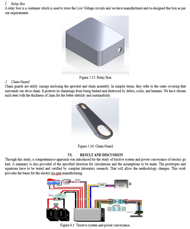
The platform adopted for the kart will be battery electric vehicle with a standard DC electric powertrain architecture as shown in Figure below. The propulsion system consists of a battery pack for the power source, motor controller for torque, and speed regulation, an electric traction motor to generate the torque and angular velocity, and a final drive to transfer the motor’s output mechanical power to the rear axle to drive the vehicle forward. An auxiliary circuit to control any vehicle accessories not associated with the operation of the powertrain is an optional extra. The DC architecture has been chosen because of its mature technology, simplicity in its operation and construction and availability of suitable light weight and compact EV components. An AC system, though providing superior torque speed characteristics, is more suited to full size production passenger road vehicles.
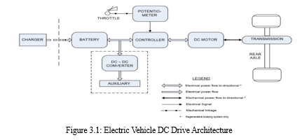
- The DC Architecture of the electric vehicle starts with the basic arrangement and planning of the components and parts that are to be placed so as to get the best desired output and efficiency of the vehicle.
- It starts with the throttle pedal and this pedal is connected to a potentiometer in the controller which controls the speed of the vehicle through different throttle levels.
- This controller is powered by the accumulator or battery pack of the vehicle so that the power can be operated and distributed based on the fluctuations.
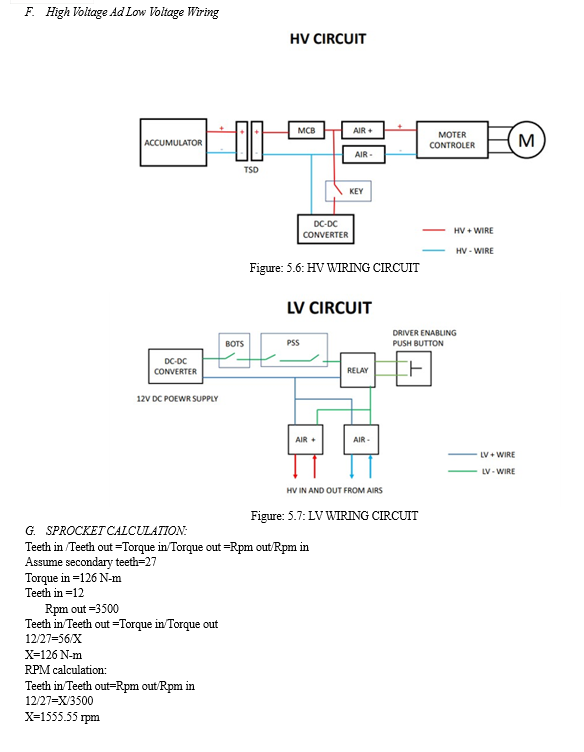
- The power goes through the DC- DC converter and amplifies it for the hv and lv circuits respectively.
- The controller acts like a control unit of the vehicle and can be used to connect the technical devices to it.
- The speedometer and other stuff like these can be connected to the controller and to display the quantities.
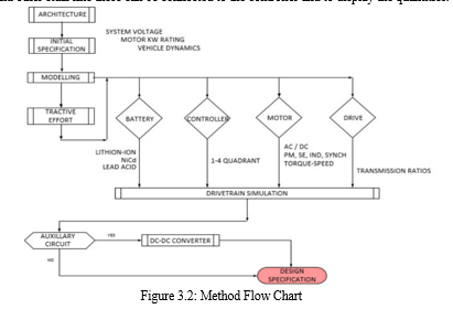
B. Problem Statement
The problem statement for the tractive system and power conveyance of an electric vehicle (EV) go-kart typically involves designing and optimizing the components responsible for transferring power from the electric motor to the wheels efficiently and identify and specify the components involved in the tractive system with the power flows to the wheels through transmission system.
IV. EXPERIMENTATION
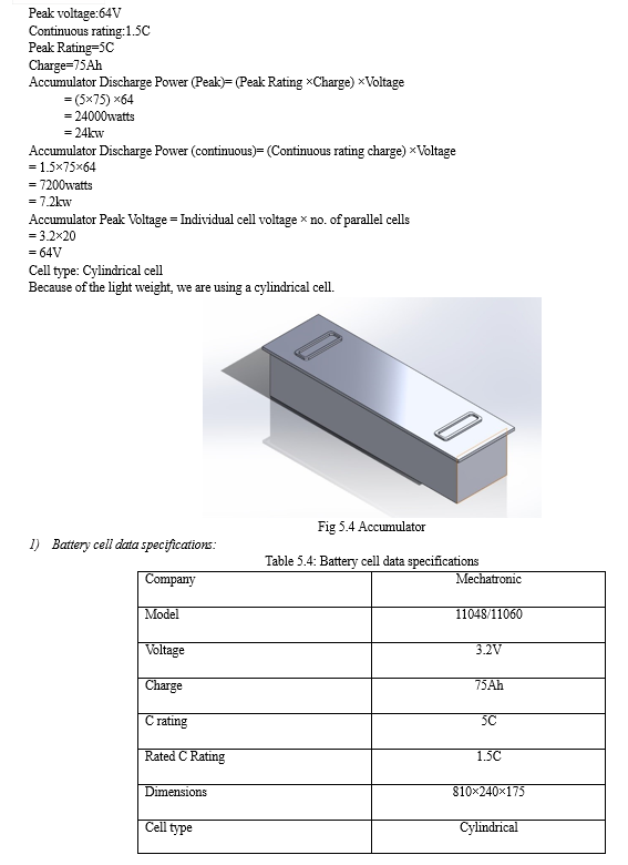
A. Accumulator
Battery packs form the core of electric vehicle technology. This chapter focuses on the two design aspects that are central to engineering reliable battery packs material selection and manufacturing method.
Batteries with high energy density, high power density, and long cycle life are needed to support the faster introduction and smooth integration of electric vehicles within our society. Choices related to both the materials used in Li-ion batteries and the methods used to manufacture the batteries influence their performance. When selecting a battery power source for a performance orientated EV drive, there are several criteria which require an assessment before any attempt at battery selection can be undertaken.
There are different types of batteries that are used in electric vehicles based on type of cells, they are:
- Lithium-Ion Batteries
- Nickel-Metal Hydride Batteries
- Lead-Acid Batteries
- Ultracapacitors
- Lithium-Ion Batteries
Very efficient and offering excellent high-temperature performance, they are currently the best option for holding a stable charge and are recyclable. Their high energy per unit mass and volume relative to other electrical energy storage systems. They also have a high power-to-weight ratio, high energy efficiency, good high-temperature performance, long life, and low self-discharge.
A battery is made up of an anode, cathode, separator, electrolyte, and two current collectors. The anode and cathode store the lithium. The electrolyte carries positively charged lithium ions from the anode to the cathode and vice versa through the separator and the movement of the lithium ions creates free electrons in the anode which creates a charge at the positive current collector. The electrical current then flows from the current collector through a device being powered to the negative current collector. The separator blocks the flow of electrons inside the battery.
a. CHARGE/DISCHARGE
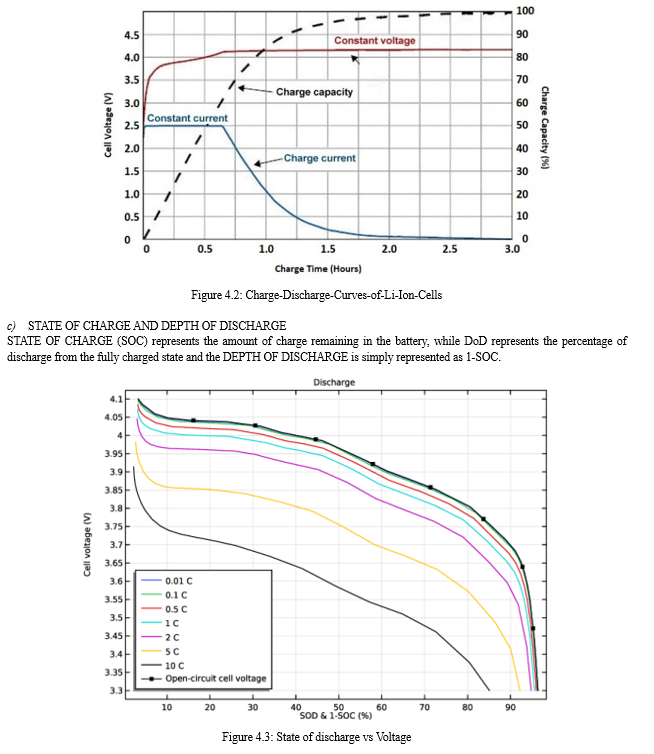
While the battery is discharging and providing an electric current, the anode releases lithium ions to the cathode, generating a flow of electrons from one side to the other. When plugging in the device, the opposite happens: Lithium ions are released by the cathode and received by the anode.
b. ENERGY DENSITY VS. POWER DENSITY
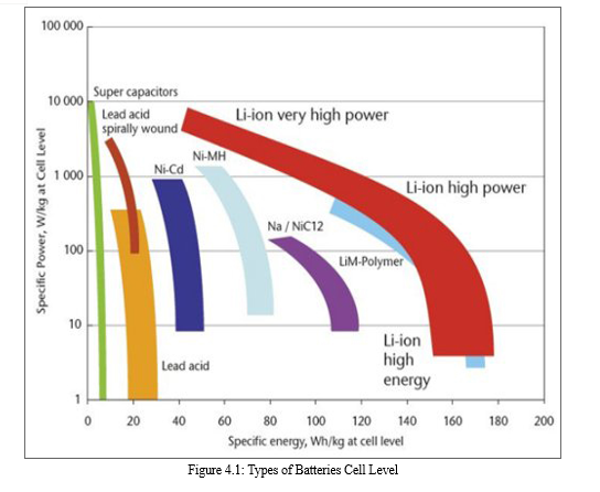
The two most common concepts associated with batteries are energy density and power density. Energy density is measured in watt-hours per kilogram (Wh/kg) and is the amount of energy the battery can store with respect to its mass. Power density is measured in watts per kilogram (W/kg) and is the amount of power that can be generated by the battery with respect to its mass. To draw a clearer picture, think of draining a pool. Energy density is like the size of the pool, while power density is comparable to draining the pool as quickly as possible.
2. Nickel-Metal Hydride Batteries
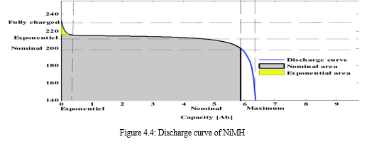
Nickel-metal hydride batteries, used routinely in computer and medical equipment, offer reasonable specific energy and specific power capabilities. Nickel-metal hydride batteries have a much longer life cycle than lead-acid batteries and are safe and abuse tolerant. These batteries have been widely used in HEVs. The main challenges with nickel-metal hydride batteries are their high cost, high self-discharge rate, heat generation at high temperatures, and the need to control hydrogen loss.
They batteries are typically used as a substitute for similarly shaped non-rechargeable alkaline batteries, as they feature a slightly lower but generally compatible cell voltage and are less prone to leaking.
a. SELF-DISCHARGE
NiMH cells have had a somewhat higher self-discharge rate than NiCd cells. The self-discharge rate varies greatly with temperature, where lower storage temperature leads to slower discharge and longer battery life. The self-discharge is 5–20% on the first day and stabilizes around 0.5–4% per day at room temperature. These has a significantly lower rate of self-discharge.
 Lead-Acid Batteries
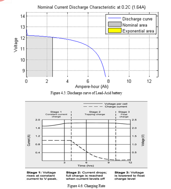
3. Lead-acid batteries can be designed to be high power and are inexpensive, safe, recyclable, and reliable. However, low specific energy, poor cold-temperature performance, and short calendar and lifecycle impede their use. Advanced high-power lead-acid batteries are being developed, but these batteries are only used in commercially available electric-drive vehicles for ancillary loads. They are also used for stop-start functionality in internal combustion engine vehicles to eliminate idling during stops and reduce fuel consumption.
Lead acid is heavy and is less durable than nickel- and lithium-based systems when deep cycled. A full discharge causes strain and each discharge/charge cycle permanently robs the battery of a small amount of capacity. This loss is small while the battery is in good operating condition, but the fading increases once the performance drops to half the nominal capacity. This wear-down characteristic applies to all batteries in various degrees.
Depending on the depth of discharge, lead acid for deep-cycle applications provides 200 to 300 discharge/charge cycles. The primary reasons for its relatively short cycle life are grid corrosion on the positive electrode, depletion of the active material and expansion of the positive plates. This aging phenomenon is accelerated at elevated operating temperatures and when drawing high discharge currents.
Charging a lead acid battery is simple, but the correct voltage limits must be observed. Choosing a low voltage limit shelters the battery, but this produces poor performance and causes a buildup of sulfation on the negative plate. A high voltage limit improves performance but forms grid corrosion on the positive plate. While sulfation can be reversed if serviced in time, corrosion is permanent. Lead acid does not lend itself to fast charging and with most types, a full charge takes 14–16 hours. The battery must always be stored at full state-of-charge. Low charge causes sulfation, a condition that robs the battery of performance. Adding carbon on the negative electrode reduces this problem but this lowers the specific energy.
These batteries are inexpensive and simple to manufacture; low cost per watt-hour, Low self-discharge; lowest among rechargeable batteries, High specific power, capable of high discharge currents, Good low and high temperature performance.
A lead battery should never be fully discharged. Lead-acid batteries can only be discharged up to 50% before irreversible damage occurs. In practice this means that you will only be able to use half of your battery capacity.
4. Ultracapacitors
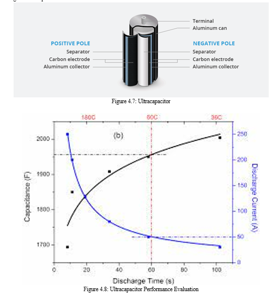
Ultracapacitors store energy in the interface between an electrode and an electrolyte when voltage is applied. Energy storage capacity increases as the electrolyte-electrode surface area increases. Although ultracapacitors have low energy density, they have very high-power density, which means they can deliver high amounts of power in a short time. Ultracapacitors can provide vehicles additional power during acceleration and hill climbing and help recover braking energy. They may also be useful as secondary energy-storage devices in electric-drive vehicles because they help electrochemical batteries level load power.
An ultracapacitor, also known as a supercapacitor or an electric double layer capacitor, is a long-lasting energy storage device that can store and release electrical energy faster than a battery. While batteries store energy through chemical reactions, standard capacitors store energy in an electric field between two electrodes like the static charge that accumulates when a balloon is rubbed against someone’s hair. However, capacitors have a very low storage capacity because they store energy in the form of electrons, which repel each other.
Ultracapacitors, on the other hand, do not store electrons directly. Instead, they store positively and negatively charged ions and use a liquid electrolyte to facilitate the flow of energy; unlike in batteries, no chemical reactions are involved. This results in much faster charge and discharge times and makes ultracapacitors ideal for automotive applications that require quick bursts of power or quick storage, such as when energy is recaptured through regenerative braking.
Ultracapacitors also have a much longer life cycle than batteries because there are no physical or chemical changes speeding up degradation. A typical battery can handle 2,000 to 3,000 charge cycles, whereas an ultracapacitor can withstand more than 1 million cycles. Ultracapacitors are more stable than batteries, do not contain heavy metals, and have an operating temperature range between -40° C and 65° C.
Ultracapacitors possess energy density that is several times higher than that of traditional capacitors. Compared with batteries, they also possess a low internal resistance (ESR), furthering their high power-density capabilities. Ultracapacitors are also capable of performing at low temperatures.
B. Motor
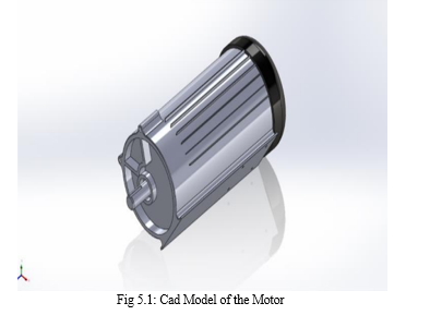
An electric motor is a device used to convert electrical energy into mechanical energy. Scientifically speaking, the electric motor is a unit used to convert electric power into motive energy or electrical energy into mechanical energy.
The most important feature of the Permanent Magnet Synchronous Motor (PMSM) is its high efficiency, given the ratio of input power after deduction of the loss to the input power. Permanent Magnet Synchronous Motors have the potential to provide high torque-to-current ratio, high power-to- weight ratio, high efficiency, and robustness. Due to the above favourable points, PMSMs are commonly used in latest variable speed AC drives, particularly in Electric Vehicle applications.
There are several types of motors used in electric vehicles, some major types are:
- DC Series Motor
- Brushless DC Motor
- Permanent Magnet Synchronous Motor (PMSM)
- Three Phase AC Induction Motors
- Switched Reluctance Motors (SRM)
- DC Series Motor
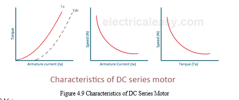
DC Series Motors are powerful and efficient, making them a popular choice for electric vehicle propulsion. These motors can vary in size depending on the specific needs of the application, but they all operate by passing direct current (DC) electricity through coils to generate a magnetic field and create rotational motion.
DC series motors have many advantages when it comes to electricity consumption; their efficiency increases as speed drops, allowing less energy consumption at lower speeds which is ideal for electric vehicles.
Additionally, they provide excellent speed control due to their simple design; this allows for precise torque output adjustment that the user can easily modify based on their needs. The cooling system of a DC series motor is also an important factor to consider in an electric vehicle context.
Since these motors produce high amounts of heat during operation, proper ventilation must be provided to ensure that temperatures remain within safe operating levels. Additionally, fans or other cooling systems may need to be installed around the motor itself in order to maintain its performance over time.
This ensures that power delivery remains consistent even after extended periods of use without any decrease in efficiency or torque output.
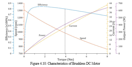
2. Brushless DC Motor
As their name implies, these motors are brushless versions of the more traditional DC motor.
This type of motor is more suitable than its predecessor due to the automation benefits it provides. The lack of brushes allows for a simpler and smaller design which improves heat management and increases operational efficiency.
Due to their efficient design, Brushless DC Motors provide a number of advantages over other types of motors in terms of cost considerations as well. They require fewer parts such as bearings since they don’t need any mechanical commutation; this helps reduce overall costs associated with manufacturing and maintenance.
Additionally, because the power circuit can be much simpler, they typically have lower energy losses resulting in higher energy savings compared to other motor designs. Finally, there’s no denying that Brushless DC Motors offer superior performance when compared to other motor types available today.
With improved reliability and longer life expectancy due to reduced friction and wear from their brushless feature, combined with increased torque density capabilities thanks to an optimal winding configuration, you can be sure that your electric vehicle will run smoothly at all times. Moreover, these motors also provide quieter operation making them ideal for applications where noise levels must remain low.
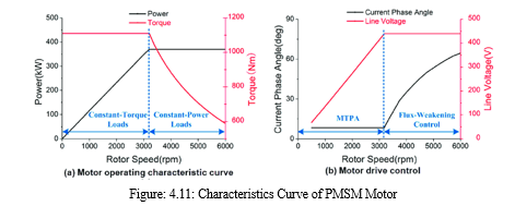
3. Permanent Magnet Synchronous Motor
PMSMs have efficiency benefits over conventional induction motors due to their high power density obtained from magnetic flux between the stator and rotor. This means they require less current than comparable induction motors in order to achieve the same output of torque or speed.
The rotor design also has advantages when it comes to torque control, as permanent magnet synchronous motors can easily be adjusted with variable frequency drives.
Another advantage of this type of motor is its flexibility in terms of configurations. A brushless DC motor consists of two main parts: a stator and a rotor. However, a PMSM can be configured into different types depending on how many poles are used in each part; single-phase or three-phase versions being the most common ones found in electric vehicles today. Additionally, there are several winding options available which allow users to customize their system according to specific requirements without compromising on performance or reliability.
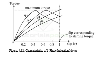
4. Three Phase AC Induction Motors
These motors feature higher torque control compared to other types of electric vehicle motors, making them ideal for applications requiring precise power output.
They also have excellent power efficiency, so they can be used in situations where energy conservation is important. In addition, these motors have a lower risk of overheating due to their cooling system design.
The downside with the three phase AC induction motor is that it has limited speed variations capabilities; therefore, this type of motor may not be suitable for all applications. Additionally, there are certain regulatory compliance issues associated with using this type of motor as well which must be taken into consideration before investing in one.
Finally, these motors tend to be somewhat more expensive than other types available on the market today.
Overall though, the advantages of choosing a three phase AC induction motor make it an attractive option when selecting components for your electric vehicle. Its high level of torque control makes it great for precision jobs while its efficient use of energy saves money in the long run.
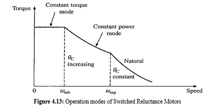
5. Switched Reluctance Motors (SRM)
You may want to consider a Switched Reluctance Motor (SRM) for its powerful torque control and cost-effectiveness, especially in situations where precise power output is needed.
SRMs are constructed with an arrangement of electromagnets that produce magnetic fields when they’re energized, which creates the mechanical force required to drive the rotor. The advantage of this design lies in its ability to vary the reluctance variation as it rotates, allowing for more accurate torque control and making operation easier compared to other types of motors. Additionally, SRMs are known for their excellent efficiency and low heat dissipation, further increasing their cost-efficiency.
Overall, SRMs offer an effective solution for electric vehicles who need precisely controlled torque or speed ratings at a lower cost point than most alternatives available today. Their simple yet robust design ensures easy operation while also providing superior performance qualities such as reduced levels of noise pollution and improved reliability over time.
With all things considered though, it’s important for you to weigh your unique needs against potential drawbacks before deciding if an SRM should be used in your application.
C. Motor Controller
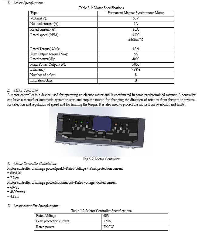
A motor controller is a device used for operating an electric motor and is coordinated in some predetermined manner. A controller can have a manual or automatic system to start and stop the motor, for changing the direction of rotation from forward to reverse, for selection and regulation of speed and for limiting the torque. It is also used to protect the motor from overloads and faults.
Motor controllers are devices that regulate the operation of an electric motor. In artificial lift applications, motor controllers generally refer to those devices used in conjunction with switchboards or variable frequency drives to control the operation of the prime mover.
The motor is controlled applying a voltage on the motor leads. The higher the voltage, the higher the speed. The direction is changed reversing the polarity on the leads. The maximum torque is limited by the current rating of the motor and it is obtained at zero speed.
A motor controller is a device or group of devices that can coordinate in a predetermined manner the performance of an electric motor. A motor controller might include a manual or automatic means for starting and stopping the motor, selecting forward or reverse rotation, selecting and regulating the speed, regulating or limiting the torque, and protecting against overloads and electrical faults. Motor controllers may use electromechanical switching, or may use power electronics devices to regulate the speed and direction of a motor.
D. Contactors or Accumulator Isolation Relays
A contactor is an electrical device that is widely used for switching circuits on and off. As such, electrical contactors form a subcategory of electromagnetic switches known as relays. A relay is an electrically operated switching device that uses an electromagnetic coil to open and close a set of contacts.
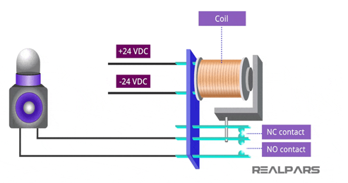
The main difference between a contactor and a relay is their load capacity. Contactors are designed to handle high currents, typically above 15 amps, while relays are more suitable for low to medium current loads, usually below 15 amps.
Contactors are devices that you can use to conduct electricity through a wire, with one type of contactor being AC and the other DC. The main difference comes in how manufacturers construct them. AC contactors have a grid arc extinguishing device, while DC has a magnetic arc extinguishing device. The contactor symbol consists of three parts: coil, main contacts and auxiliary contacts. There can only be one coil in a contactor. The main contacts of a contactor are three and are always drawn as one symbol in the form of three contacts.
E. MCB And Tractive System Disconnect (TSD)
- MCB
A miniature circuit breaker (MCB) is an Electrical Switch that automatically switches off the electrical circuit during an abnormal condition of the network means an overload condition as well as a faulty condition. Nowadays MCB is widely used in a low-voltage electrical network instead of a fuse. The fuse may not sense it but the miniature circuit breaker does it in a more reliable way. MCB is much more sensitive to overcurrent than a fuse.
Whenever continuous overcurrent flows through MCB, the bimetallic strip is heated and deflects by bending. This deflection of the bi-metallic strip releases a mechanical latch.
As this mechanical latch is attached to the operating mechanism, it causes to open the miniature circuit breaker contacts, and the MCB turns off thereby stopping the current to flow in the circuit. To restart the flow of current the MCB must be manually turned ON.
This mechanism protects from faults arising due to overcurrent or overload and short circuits.
But during short circuit conditions, the current rises suddenly, causing electromechanical displacement of the plunger associated with a tripping coil or solenoid. The plunger strikes the trip lever causing the immediate release of the latch mechanism consequently opening the circuit breaker contacts. This was a simple explanation of a miniature circuit breaker’s working principle.
An MCB is very simple, easy to use, and is not generally repaired. It is just easier to replace. The trip unit is the main part, responsible for its proper working. There are two main types of trip mechanisms. A bimetal provides protection against overload current, and an electromagnet provides protection against electric short-circuit current.
There are different types of MCB’s used based on electrical protection system, they are from Type A- Type K and based on factors, there are like Thermal, Magnetic, Hybrid, Electronic, Differential, RCCB and Isolation.
2. TSD
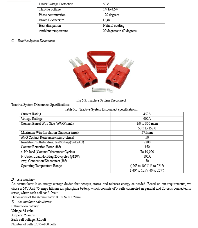
Tractive system Disconnect connector is commonly known as the fourth safety device used within a high voltage battery pack. This device is a method for breaking the electrical continuity within the pack for the purpose of vehicle service. The MSD is often a touch safe, removable enclosure containing the fuse.
Depending on which kind of battery pack and which kind of Manual Service Disconnect is used, we would provide different sealing solutions including consultants in materials and systems.
There are different types of disconnect switches, they are:
- Fused Load Break Switch.
- Manual Disconnect Switch.
- Manual Disconnect Switch.
- Motor Operated Disconnect Switch.
- Air Disconnect Switch.
- Vertical Break Disconnect Switch.
- Centre Break Disconnect Switch.
- High Voltage Disconnect Switch.
F. Battery Management System (BMS)
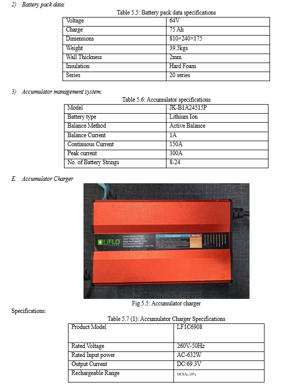
Battery management system (BMS) is technology dedicated to the oversight of a battery pack, which is an assembly of battery cells, electrically organized in a row x column matrix configuration to enable delivery of targeted range of voltage and current for a duration of time against expected load scenarios.
The oversight that a BMS provides usually includes:
Monitoring the battery
Providing battery protection
Estimating the battery’s operational state
Continually optimizing battery performance
Reporting operational status to external devices.
G. Drive Shaft
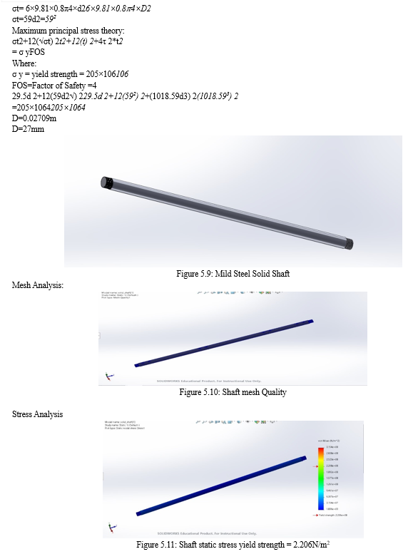
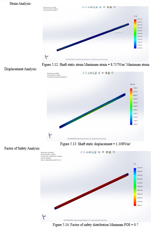
The drive shaft, also called propeller shaft or prop shaft is a component of the drive train in a vehicle, with the purpose of delivering torque from the transmission to the differential, which then transmits this torque to the wheels to move the vehicle.
The drive shaft is primarily used to transfer torque between components that are separated by a distance, since different components must be in different locations in the vehicle. A front-engine rear-wheel drive car must have a long drive shaft connecting the rear axle to the transmission since these parts are on opposite sides of the car.
Drive shafts are used differently in different vehicles, varying greatly in cars with distinct configurations for front-wheel drive, four-wheel drive, and the previously mentioned front-engine rear-wheel drive. Other vehicles also use drive shafts, like motorcycles, locomotives, and marine vessels. Below is the drive shaft configuration for a common front-engine rear-wheel drive vehicle. In a go-kart the drive shaft is also the rear axle of the vehicle connecting through different drives from motor to the wheels.
There are different types of shaft materials used, some of commonly used materials are Mild Steel, Stainless Steel and Heat Treated Steel.
Apart from these, there are many types of materials used based on the parameters and however these types also have different grade qualities used to represent different properties.
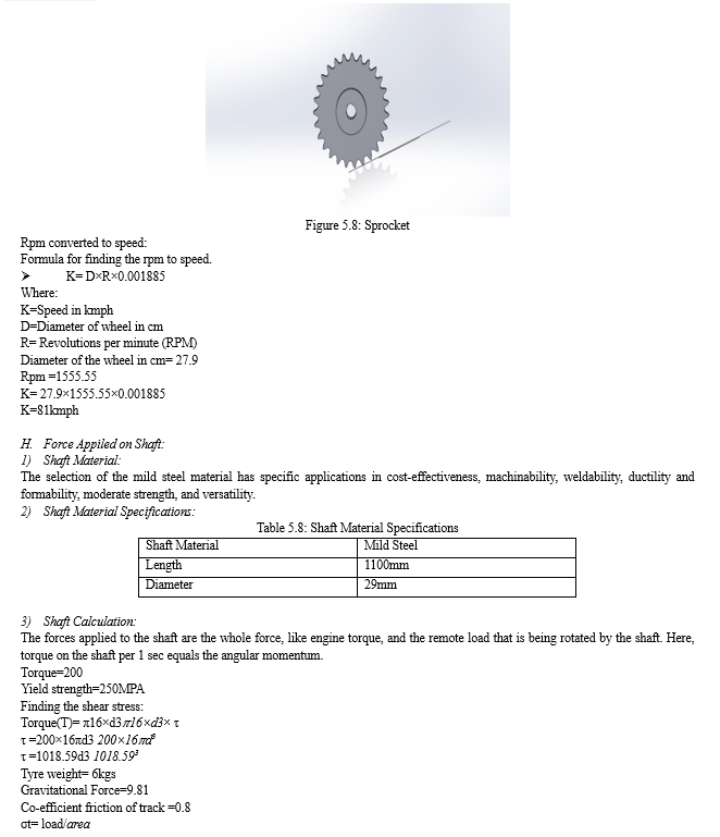
H. SPROCKET
A Sprocket is a toothed wheel whose teeth engage the links of a chain. Sprockets are designed to directly move something such as a chain or belt, so they work more independently. A Sprocket is used to receive the power from the motor and provide it to the shaft by means of chain drive and a secondary sprocket.
The primary and secondary sprocket are selected based on the calculations to the requirements and no of teeth needed.
The most commonly used material for the manufacturing of sprocket is mild steel but of different grades. The sprocket size represents the first two digits in the chain designation.
V. SELECTION OF COMPONENTS
A. Motor
An electric motor is a device used to convert electrical energy into mechanical energy. Scientifically speaking, the electric motor is a unit used to convert electric power into motive energy or electrical energy into mechanical energy.
The most important feature of the Permanent Magnet Synchronous Motor (PMSM) is its high efficiency, given the ratio of input power after deduction of the loss to the input power. Permanent Magnet Synchronous Motors have the potential to provide high torque-to-current ratio, high power-to- weight ratio, high efficiency, and robustness. Due to the above favorable points, PMSMs are commonly used in latest variable speed AC drives, particularly in Electric Vehicle applications.
VII. FUTURE SCOPE
The potential market of the electric go-karts beyond recreational racing such as urban track simulations, education programs and urban mobility gives promising opportunities for commercialization and deployment. This can be improved on the aspects like Efficiency Improvement, Integration with Renewable Energy, Safety Enhancements, Miniaturization and Lightweight Design in the future and made better.
VIII. ACKNOWLEDGMENT
We owe our immense thanks to Dr. B. VIJAYA KUMAR our guide, Professor and Head of the Mechanical Engineering, & COE Guru Nanak Institute of technology for the sustained interest, constructive criticism, and constant encouragement at every stage of this endeavour.
We extend our deep sense of graduate to Dr. B. VIJAYA KUMAR, Professor & Head of the Mechanical Department & COE.
We owe our immense thanks to Dr. S. SREENATHA REDDY, Principal and the management of the Guru Nanak Institute of Technology for providing us the best amenities which enabled us to complete our project in the stipulated time.
Finally, yet importantly, we are very thankful to our parents, friends, and other faculty of Mechanical Engineering department for their constant support in completion of this project.
Conclusion
The main aspect of the study is the tractive system and power conveyance of the electric go kart; this includes the efficiency, selection process, methodology and effectiveness of the system in various conditions. This paper also gives the practical implications in development and operation of the electric go-kart. There are several factors to be considered that are common to all or any engineering vehicles. With an approach of engineers can come up with the most effective possible product for the society. The chosen methodology of the tractive system gives the best effectiveness of the system and all the parameters like Reliability, safety, Cost, Performance, aesthetics, ergonomics, Standard dimensions & material were also taken in consideration on an equivalent time which gives the study more effective towards the society.
References
[1] C. C. Chen, “An overview of electric vehicle technology,” Proceeding of IEEE, vol. 81, no.9, pp. 1202-1213, Sept 1993. [2] C. Cardoso, J. Ferriera, V. Alves, R. E. Araujo, “The design and implementation of an electric go-kart for education in motor control, “IEEE International SPEEDAM 2006, pp. 1489 – 1494, May 2006. [3] F. J. Perez-Pinal, C. Nunez, R. Alvarez, M. Gallegos, “Step by step design procedure of an independent-wheeled small EV applying EVLS,” IECON 2006-32nd Annual Conference on IEEE Industrial Electronics, pp. 1176-1181, Nov 2006. [4] M. Xianmin, “Propulsion system control and simulation of electric vehicle in MATLAB software environment, “Proceeding of the 4th World Congress on Intelligent Control and Automation 2002, pp. 815-818, June 2002. [5] M. Lee, B. H. Co, “Modeling and simulation of electric Vehicle power system, “Proceeding of the 32nd Intersociety IECEC -97, vol. 3, pp. 2005-2010, August 1997 [6] Y. Ding, Z. Cano, A. Yu, J. Lu and Z. Chen, Automotive Li-Ion Batteries: Current Status and Future Perspectives, Electrochemical Energy Reviews, 2019, Vol. 2, Issue 1, pp. 1-28 [7] L. Ahmadi, S.B. Young, M. Fowler, R.A. Fraser Reuse of electric vehicle lithium-ion battery packs in energy storage systems International Journal of Life Cycle Assessment, 22 (1) (2015), pp. 1-14 [8] Aniket Rameshwar Gade, \"The New Battery Management System in Electric Vehicle\", IJERT, vol. 10, no. 07, July-2021 [9] A. Hariprasad, Priyanka, V. Sandeep and Shekar Ravi, \"Battery Management System in Electric Vehicles\", IJERT, vol. 9, no. 05, May-2020. [10] Ananthraj C R, Arnab Ghosh, ‘Battery Management System in Electric Vehicle’ International Conference on Nascent Technologies in Engineering (ICNTE) [11] Gheorghe Livint; Florin A.Rusu; Cosmin G. Pintilie, \' Algorithm for Estimating SOC of Lithium-Ion Batteries Used for Electric Vehicles. [12] Gheorghe Livint; Florin A.Rusu; Cosmin G. Pintilie, ‘Algorithm for Estimating SOC of Lithium-Ion Batteries Used for Electric Vehicles’ International Symposium on Advanced Topics in Electrical Engineering (ATEE) [13] Jeevak S. Lokhande; P. M. Daigavhane; Mithu Sarkar,’ A Critical Approach Towards a Smarter Battery Management System for Electric Vehicle’ International Conference on Trends in Electronics and Informatics (ICOEI)(48184) [14] Saurabh Shah; Meera Murali; \'Priyanka Gandhi A Practical Approach of Active Cell Balancing in a Battery Management System\' International Conference on Power Electronics, Drives and Energy Systems (PEDES). [15] Parikshith Savanth; Shailesh K.R,\'Reduction of parameters in a Lithium-ion cell model by experimental validation of relationship between OCV and SOC\' International Conference on Green Engineering and Technologies (IC-GET) [16] S. Sakunthala; R. Kiranmayi; P. Nagaraju Mandadi,\'A study on industrial motor drives: Comparison and applications of PMSM and BLDC motor drives\' International Conference on Energy, Communication, Data Analytics and Soft Computing (ICECDS) [17] R. M. Pindoriya; B. S. Rajpurohit; R. Kumar; K. N. Srivastava,\'Comparative analysis of permanent magnet motors and switched reluctance motors capabilities for electric and hybrid electric vehicles\'IEEMA Engineer Infinite Conference (eTechNxT) [18] Mohan. S; S. Sumitha; Gunavathi. G; Prathish Kumar. U; Azhagumurugan. R; Tejas Kanna. G,\'Improving Torque in PMSM by Introducing Flux Barrier\' International Conference on Power, Energy, Control and Transmission Systems (ICPECTS). [19] Kalpana Chaudhary; Piyush Singh; Abhay Janardan Singh,\' Fuel cell Input Based PMSM Motor Drive for Electric Vehicle Applications\' IEEE 3rd International Conference on Smart Technologies for Power, Energy and Control (STPEC) [20] Yubin He; Zhihao Gu; Chao Zhang; Wanbin Ren, \'Investigation of the degradation process and failure mechanisms of AC contactor in the electrical endurance experiential’, 68th Holm Conference on Electrical Contacts (HOLM) [21] Gu Ao; Zhang Qiang; Huang Haitai; Hong Yongbin, \'Optimization Design of Contactor Driver for Electric Vehicle\',IEEE 2nd International Power Electronics and Application Symposium (PEAS) [22] Dongmei Yuan; Qiang Liang; Xihong Zou, \'Design on torsion test-bed of automobile drive shaft\',Second International Conference on Mechanic Automation and Control Engineering [23] Artem Ermolaev; Aleksandr Plekhov; Dmitriy Titov; Yuriy Vagapov, \'Vibration damping in a motor drive shaft system operating under active power flow oscillation\',IEEE Conference of Russian Young Researchers in Electrical and Electronic Engineering (EIConRus)
Copyright
Copyright © 2024 B. Pavan Kalyan , B. Adithya, D. Sai Venkat Ruthviz, P. Nagesh, Dr. B. Vijaya Kumar. This is an open access article distributed under the Creative Commons Attribution License, which permits unrestricted use, distribution, and reproduction in any medium, provided the original work is properly cited.

Download Paper
Paper Id : IJRASET61036
Publish Date : 2024-04-26
ISSN : 2321-9653
Publisher Name : IJRASET
DOI Link : Click Here
 Submit Paper Online

