

Ijraset Journal For Research in Applied Science and Engineering Technology
Super-Lift Luo-Converter with Integration of Buck Converters for EV Applications
Authors: Aneesrahman T, Rasnas , Shefni
DOI Link: https://doi.org/10.22214/ijraset.2025.66356
Certificate: View Certificate
Abstract
In this work, a super-lift and buck converter (SLBC) are integrated to provide a DC-DC multi-port converter. The single-input dual-output (SIDO) converter under consideration provides benefits over typical positive output voltage super-lifting while concurrently producing step-up and step-down voltages using buck and Luo converters. The ripple in output voltages is reduced to a minimum in this construction by generating a dual output without using electromagnetic components. The newly launched SLBC, presently, features simple layout and a reliable control strategy that offers a wide variety of output voltages. Additionally, in order to highlight the benefits of the proposed SIDO converter, a comparison with other equivalent setups is made. Results from simulations and experiments show a significant decrease in conduction losses when compared to other SIDO converters in the similar circumstances. By running a number of simulations in the MATLAB/Simulink programme and putting a 7.5W prototype through testing in the lab, the operating correctness of SLBC is verified.
Introduction
I. INTRODUCTION
In response to increasing concerns about environmental pollution and the depletion of fossil fuels, the development of electric vehicles (EVs) has become an increasingly popular trend. The adoption of high-performance and dependable power electronics systems is essential to enhancing the performance and efficiency of EVs. In this context, a proposed solution for the voltage conversion needs of EVs is the Super-lift Luo-converter with the integration of Buck converters (SLBC).
High step-up voltage gain, minimal switching losses, and low output voltage ripple are benefits of the suggested converter. In order to assess the suggested converter's performance and suitability for EV applications, this project will construct and simulate it. The simulation findings will support the suggested converter's viability and effectiveness and offer guidance for applying it to real-world EV systems.
In recent years, DC-DC multi-port converters (MPCs) have been a hot topic due to the growing industry of electric vehicles (EVs) and higher penetration of renewable energy sources (RESs) such as photovoltaics (PV) incorporated with wide voltage ranges. DC-DC MPCs are divided into two different structures: multi-inputs and multi-outputs. Multi-inputs structures are applied to supply a load utilizing different sources.
On the other hand, multi-outputs supply various voltage levels by a single source. These types of converters are used in RESs, mobile transmission, LED drivers and EVs. The field of DC-DC converters has been interested in single input dual output (SIDO), or single-input multi-output, converters. In the literature, a variety of architectures have been proposed, including those with connected inductors, single-inductor multi-output arrangements, and multi-port transformers. However, these architectures have drawbacks including large components, significant losses, and complex drive and control circuits.
When compared to other topologies with an identical design, the SLBC exhibits a considerable reduction in conduction losses. The suggested construction is capable of meeting the varied voltage requirements of electric vehicle systems. The SLBC offers a broad variety of output voltages and has an effective control strategy. Additionally, it eliminates the requirement for electromagnetic components to provide two outputs, hence simplifying the design. Also, the proper functioning of the SLBC in producing two separate step-up and step-down outputs with little output ripple is confirmed by simulations and experimental findings.
In this regard, the SLBC is a promising structure for SIDO converters, providing benefits in terms of design simplicity, minimal conduction losses, and adaptability in output voltage range.
II. SYSTEM CONFIGURATION
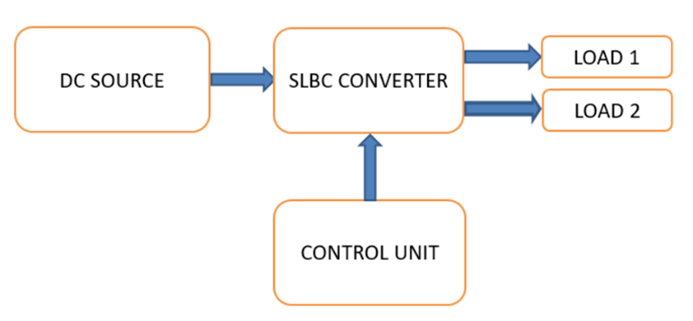
Fig. 1. Block diagram of the system
Block diagram of proposed DC-DC multi-port converter consist of DC source, SLBC converter, control unit, loads. The block diagram of proposed converter is shown in Fig.1.This paper creates a SIDO DC-DC converter with two different boost and buck outputs. Various components in an EV, such as the motor, sound system, and lamps, require different voltages. Therefore, the appropriate application for promoting the model is the EV. Recommended DC-DC Converter Integrated Super lift and a Buck Converter (SLBC) produce both boost and buck outputs from a single input. The output power is increased by the super lift method. In this way, high gain voltage can be created with a simple structure without an additional transformer or circuit for control, regulation. Therefore, the generated output voltage has better power ef?ciency. In the proposed converter, the positive output super-lift Luo-converter is utilized for the step- up output. Meanwhile, the proposed SIDO converter can provide step-down voltage. The structure of the proposed converter is shown in Fig.2
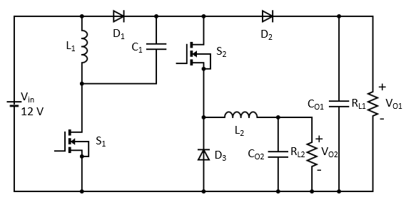
Fig. 2. Schematic diagram of the system
A super-lift Luo-converter is a modification of the basic Luo-converter design that includes an additional voltage boost stage, which allows for even higher step-up voltage ratios. By integrating the buck converter (another type of DC-DC converter), the output power can be more controlled and efficient; this is electric vehicles Fab. In electric vehicles, the power electronics system must convert the high voltage of the battery to the low level required by the various vehicle components. The super lift converter can increase the battery voltage to a higher level, which can be reduced to a suitable level for special components by the buck converter. This approach reduces power loss and maximizes overall efficiency, which is especially important in electric vehicles where battery life and range are important. Overall, the super-lift Luo converter with integrated buck converter can be a more efficient and compact solution for high-power DC-DC conversion in electric vehicles. The Luo converter and buck converter combination uses the Luo converter as a high-voltage, high-gain stage and the buck converter as a low-voltage, low-gain stage. The output of the Luo converter is connected to the input of the buck converter, and the combination of the two converters results in an efficient and accurate step-up and step-down power conversion.
A. The proposed SLBC operation modes
1) MODE-1
- In this modes switches S1 and S2 are ON
- Switch S1 connects the input voltage to inductor L1.
- Inductor L1 starts to store energy in the form of a magnetic field
- This causes a voltage increase across the inductor L1, which is then transmitted through diode D1 to capacitor C1.
- Capacitor C1 charges through diode D1, and a portion of this voltage passed to switch S2 which conducts and charges inductor L2,
- Capacitor CO2 also charges with inductor L2 and output is taken across resistor RL1.
- This time Diodes D2 and D3 are reverse biased.
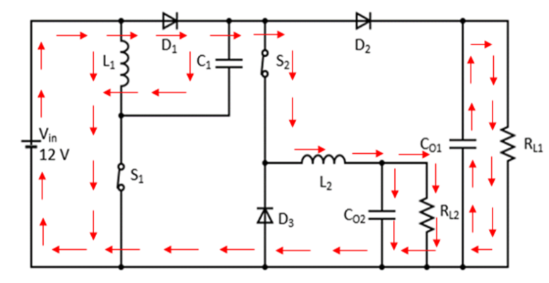
Fig. 3 Mode -1 of proposed SLBC converter
2) MODE-2
- In this mode switch S1 is ON and S2 is OFF
- When S2 is OFF, inductor L2 starts to discharge through diode D3 and charges capacitor CO2.
- Diode D3 is now forward biased.
- Output is taken across resistor RL2.
- This time L1 and C1 continues charging as in mode-1 due to S1 is turned on.
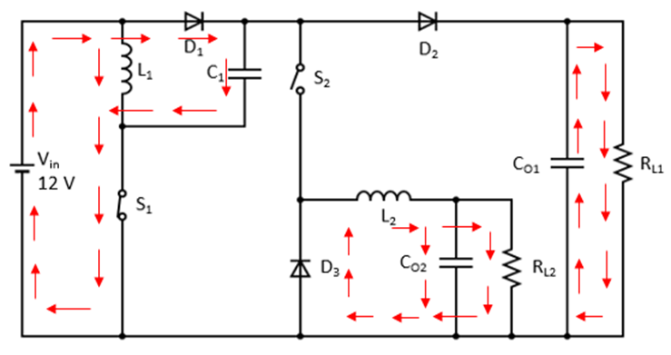
Fig. 4 Mode -2 of proposed SLBC converter
3) MODE-3
- In this mode switches S1 and S2 are OFF.
- When switch S1 is turned off, Inductor L1 starts to discharge as its polarity is reversed.
- Diode D2 is now forward biased and capacitor CO1 charges.
- Super lifted output voltage VO1 shows across load RL1.
- This VO1 is the sum of Vin, VL1 and VC1.
- Switch S2 remains turned OFF in this mode so inductor L2 continues to discharge through Diode D3 and charges capacitor CO2.
- The average value of CO2 charging in two modes is taken as the step downed output voltage VO2.
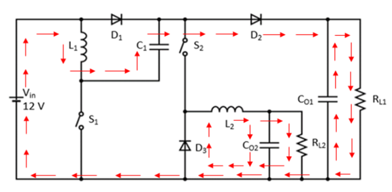
Fig.5 Mode -3 of proposed SLBC converter
III. PERFORMANCE ANALYSIS OF THE SYSTEM
In our Super-lift Luo converter integrated buck converter project, we use MATLAB to simulate and control the performance of our proposed converter. MATLAB simulation is a powerful tool widely used in the electrical and electronic engineering industry to analyze, design and test different circuits and systems. It provides a comprehensive introduction to the design, simulation and analysis of complex systems, including electrical power systems. Through simulation we can analyze the behavior of the converter under different operating conditions, optimize its performance and evaluate its efficiency.
In the simulation model of the Super-lift Luo converter with integrated buck converter, closed-loop control of the MOSFET switch is performed. This provides better control of the output voltage and keeps it in range even if there are variations in the input voltage or load. The closed loop control system includes a feedback loop that monitors the output voltage and compares it to a reference voltage. Any difference between the two voltages is fed into the controller, which adjusts the duty cycle of the MOSFET switches in order to maintain a stable output voltage. The controller used in the simulation is a proportional-integral-derivative (PID) controller that takes into account the current error and the rate of change of the error experience and adjusts the duty cycle accordingly. The parameters of the PID controller can be tuned to optimize the response time and stability of the system. The simulated diagram is shown in the fig.6.It enables independent controlling of two switches in the SLBC converter. As we mentioned above closed loop control mechanism ensures regulating of super-lifted output voltage and buck output voltage effectively. By correct tuning of PID controller separate, control of two switches are possible. PID control helps to control two switches independently to keep the system running at high efficiency. The PID control algorithm adjusts the duty cycle of the switches to maintain the desired voltage while minimizing the effects of interference and noise in the system. The simulated model of SLBC have six times gain for the super-lifted output voltage and a wide range of voltage for buck output.
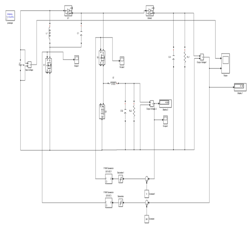
Fig.6 Simulated circuit diagram
Simulation waveforms are important for understanding the behavior of the super-lift Luo-converter with the integration of buck converter. Input voltage waveform shows the behavior of the input voltage over time and output voltage waveform shows the behavior of the output voltage over time. Simulated waveforms can provide information about the ripples in the circuit. These waveforms provide a visual representation of the circuit's behavior and can be used to analyze the circuit's performance under different operating conditions. The simulation waveforms obtained for SLBC is shown fig.7 and fig.8.
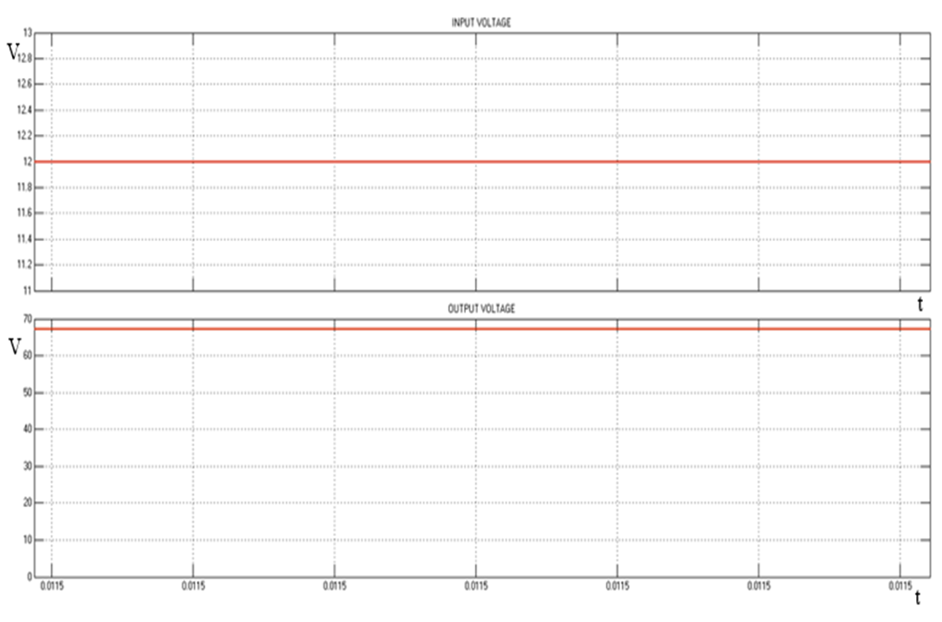
Fig.7 Input voltage waveform and super-lifted output voltage waveform
Fig.7 includes input voltage waveform and super-lifted output voltage waveform of the simulated model of SLBC. Fig 8 shows step downed (buck) output voltage waveform of the simulated model of SLBC.
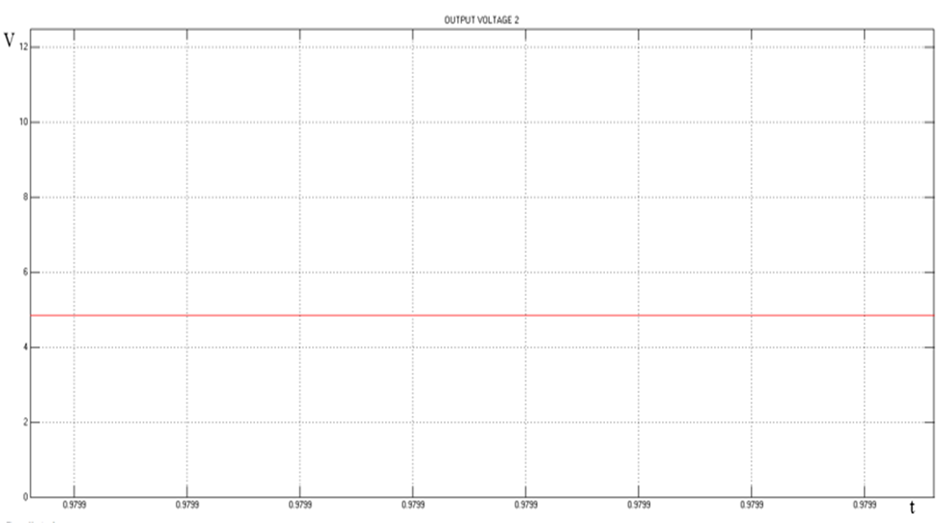
Fig.8 Step downed (buck) output voltage waveform
IV. DESIGN OF THE SYSTEM
This section discuss the design of a 10w SLBC converter prototype. The rating and specifications of components used design of
prototype are as follows:
A. Design Of Super-Lift LUO Converter
Input voltage Vin = 12V
Output voltage VO1= 68V
Output power=5W
Switching frequency = 30kHz
Efficiency = 90%
Voltage transfer gain = VO1Vin =2-D1-D
= 6812  = 2-D1-D
Duty ratio D = 0.786
Here Pin = 5.56 W
Inductor current IL = 0.463A
Current ripple of L1 is = 40% of IL
= 0.185 A
Desired size of inductor L1 = VinDT?IL
= 12 × 0.786× 33.33×10_60.185
=1.69mH
Desired size of capacitor C1 = 1-DVOf ?VO R
= (1-0.786)×6830000×68×0.01×924.8
= 7.71μF
Desired size of capacitor CO1 = IO×Dfs?VOR
= (568)×0.78630000×68×0.01
= 2.83μF
B. Design Of Buck Converter
Input voltage Vin = 68V
Output voltage VO2= 5V
Output power=2.5W
Switching frequency = 30kHz
Efficiency = 90%
Here Pin = 2.77W
Duty ratio D = VO2Vin
= 568
= 0.0735
Desired size of inductor L2 = (Vin-VO2)DT?I
= (68-5)×0.0735×33.33×10-60.1×0.4
= 3.85mH
Desired size of capacitor CO2 = IO?V4f
= (2.55)0.01×5×4×30000
= 83μ F
F
To justify the theoretical analysis of the proposed SLBC converter producing a boosted 68V and step downed 5V output voltages from a 12V dc input supply prototype is developed in laboratory. The prototype operating at a switching frequency of 30 kHz and have a 7.5W output power. For high-speed and high-power operation MOSFET IRF530 and p55 are utilized in our prototype as power switches. The developed hardware is shown in the fig.9.
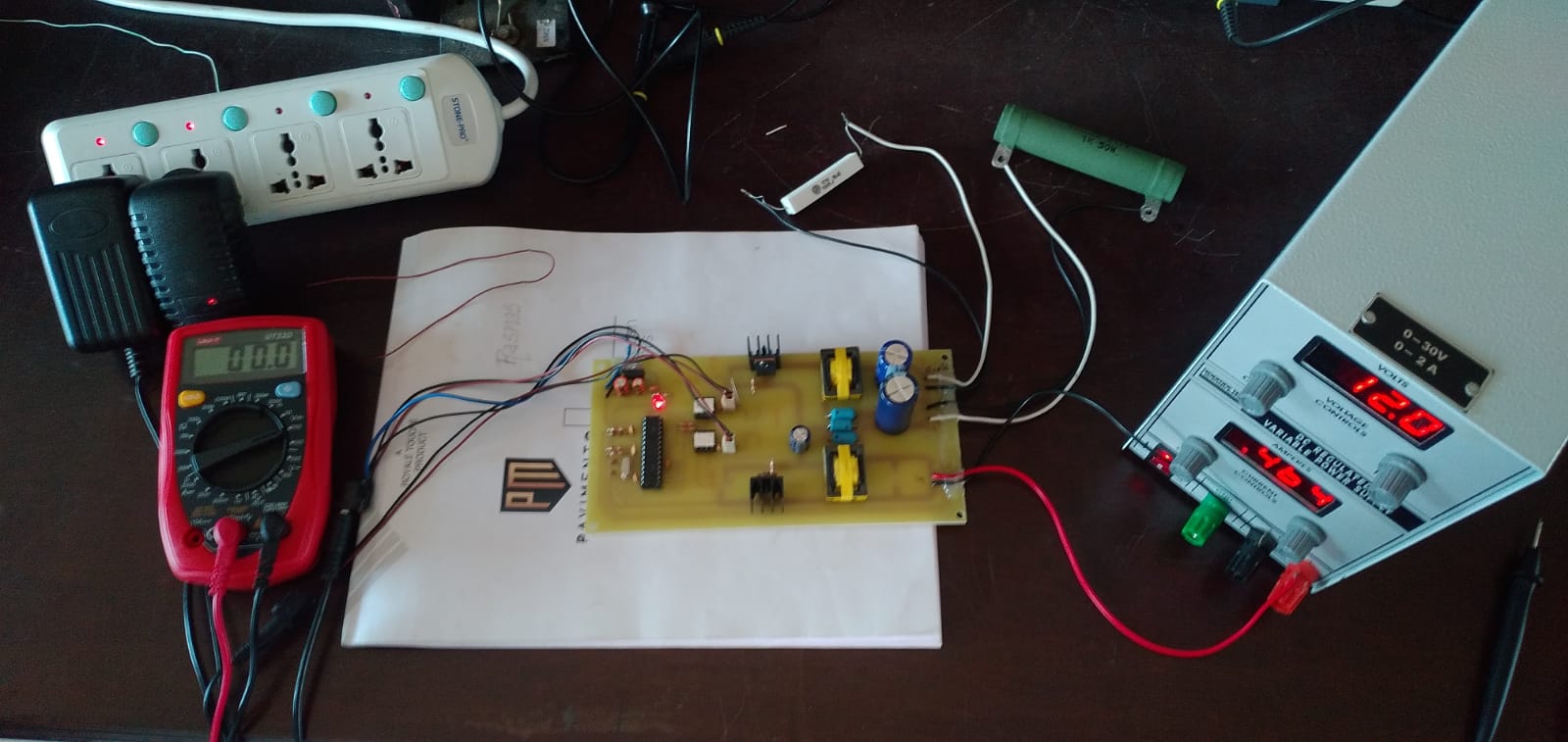
Fig.9 Experimental prototype of proposed SLBC converter
The specifications of the components used in prototype are listed in table 1
Table 1 Design specification of the prototype
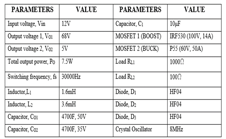
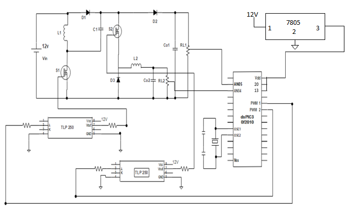
Fig10 Schematic diagram
The output voltage of the proposed SLBC converter prototype made in the laboratory is shown in the fig.11 and fig 12 .The output voltage measured across the 1000Ω load is 68V is shown in figure 5.5.3, which is the super lifted output. In the proposed converter we achieved six times output voltage gain. The output voltage measured across the 100Ω load is 5V as shown in fig.5.5.4, which is the buck output. We also understood that the range of buck output is increased from minimum to maximum value. Two outputs having almost less amount of ripples are resulted in the voltage waveforms. The proposed SLBC converter is proved to be more efficient (90%) and have simplest design with lesser number of components ensures its practicality.
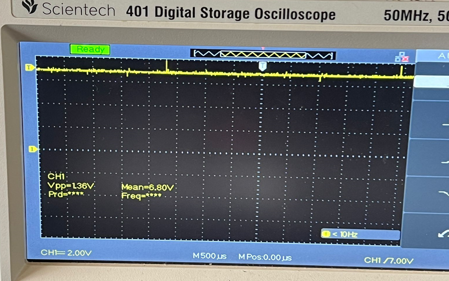
Fig.11 Super-lifted output voltage waveform of the prototype
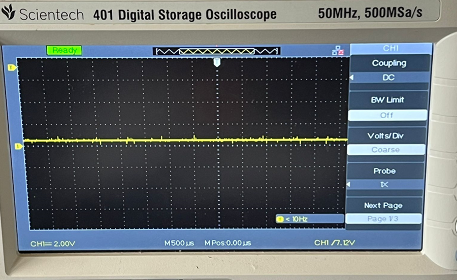
Fig.12 Buck output voltage waveform of the prototype
Conclusion
In conclusion, it has been successful to build a super-lift Luo-converter with the integration of buck converters for use in electric vehicle applications. The research offers a remedy for both high-voltage and low-voltage uses in an electric vehicle, increasing its dependability and efficiency. The project was able to show that the Super-lift Luo-conversion and Buck converter are successful at generating the appropriate output voltages via the use of simulation and hardware implementation. The MOSFET switches are able to be independently controlled by the closed-loop control system utilizing the PID controller, leading to reliable and effective operation. Our suggested converter successfully achieves its primary goals of generating a wide range of voltage, enhanced voltage gain, and minimal conduction losses without the use of electromagnetic devices. It is possible to transmit power and regulate voltage effectively by using a single input multi output (SIMO) converter with various output voltage levels. Electric vehicles can utilize use of the converter\'s properties, such as high efficiency, decreased size and weight, and increased dependability, according to the suggested design and specifications. Advanced control techniques can also be used to further optimize the suggested converter\'s functionality and efficiency. Overall, the SIMO DC-DC converter under consideration has enormous potential applications in the fields of electric vehicles and renewable energy systems.
References
[1] S. Habib, M. M. Khan, F. Abbas, A. Ali, M. T. Faiz, F. Ehsan, and H. J. Tang, “Contemporary trends in power electronics converters for charging solutions of electric vehicles,” CSEE Journal of Power and Energy Systems, vol. 6, no. 4, pp. 911–929, Dec. 2020. [2] A. Alahyari, M. Fotuhi-Firuzabad, and M. Rastegar, “Incorporating customer reliability cost in PEV charge scheduling schemes considering vehicle-to-home capability,” IEEE Transactions on Vehicular Technology, vol. 64, no. 7, pp. 2783–2791, Jul. 2015. [3] B. R. Lin, “DC–DC converter implementation with wide output voltage operation,” Journal of Power Electronics, vol. 20, pp. 376–387, Mar.2020. [4] G. P. Chen, Y. W. Liu, X. L. Qing, M. Y. Ma, and Z. Y. Lin, “Principle and topology derivation of single-inductor multi-input multi-output DCDC converters,” IEEE Transactions on Industrial Electronics, vol. 68,no. 1, pp. 25–36, Jan. 2021. [5] P. KhademiAstaneh, J. Javidan, K. Valipour, and A. Akbarimajd, “A bidirectional high step-up multi-input DC-DC converter with soft switching,” International Transactions on Electrical Energy Systems, vol. 29, no. 1,pp. e2699, Jan. 2019. [6] G. D. Li, J. Xia, K. Wang, Y. Deng, X. N. He, and Y. S. Wang, “Hybrid modulation of parallel-series LLC resonant converter and phase shift full-bridge converter for a dual-output DC-DC converter,” IEEE Journal of Emerging and Selected Topics in Power Electronics, vol. 7, no. 2, pp. 833–842, Jan. 2019. [7] Z. H. Shen, X. G. Chang, W. W. Wang, X. Tan, N. Yan, and H. Min, “Predictive digital current control of single-inductor multiple-output converters in CCM with low cross regulation,” IEEE Transactions on Power Electronics, vol. 27, no. 4, pp. 1917–1925, Apr. 2012. [8] B. Faridpak, A. Alahyari, M. Farrokhifar, and H. Momeni, “Toward small scale renewable energy hub-based hybrid fuel stations: Appraising structure and scheduling,” IEEE Transactions on Transportation Electri?cation, vol. 6, no. 1, pp. 267–277, Mar. 2020. [9] T. Kim, O. Vodyakho, and J. Yang, “Fuel cell hybrid electric scooter,” IEEE Industry Applications Magazine, vol. 17, no. 2, pp. 25–31, Mar. /Apr. 2011 [10] F. Gao, B. Blunier, M. G. Simoes, and A. Miraoui, “PEM fuel cell stack ˜ modeling for real-time emulation in hardware-in-the-loop applications,” IEEE Transactions on Energy Conversion, vol. 26, no. 1, pp. 184–194, Mar. 2011. [11] H. Haga and F. Kurokawa, “Modulation method of a full-bridge three- level LLC resonant converter for battery charger of electrical vehicles,” IEEE Transactions on Power Electronics, vol. 32, no. 4, pp. 2498–2507, Apr. 2017. [12] H. F. Wu, C. G. Wan, K. Sun, and Y. Xing, “A high step-down multiple output converter with wide input voltage range based on quasi two-stage architecture and dual-output LLC resonant converter,” IEEE Transactions on Power Electronics, vol. 30, no. 4, pp. 1793–1796, Apr.2015. [13] M. X. Chen and E. K. W. Cheng, “Derivation, analysis and development of coupled-inductor-based non-isolated DC converters with ultra-high voltage-conversion ratio,” IET Power Electronics, vol. 11, no. 12, pp. 1964–1973, Oct. 2018. [14] R. J. Wai and K. H. Jheng, “High-ef?ciency single-input multiple-output DC-DC converter,” IEEE Transactions on Power Electronics, vol. 28, no. 2, pp. 886–898, Feb. 2013. [15] D. Kwon and G. A. Rincon-Mora, “Single-inductor-multiple-output switching DC-DC converters,” IEEE Transactions on Circuits and Systems II: Express Briefs, vol. 56, no. 8, pp. 614–618, Aug. 2009. [16] P. Patra, A. Patra, and N. Misra, “A single-inductor multiple-output switcher with simultaneous buck, boost, and inverted outputs,” IEEE Transactions on Power Electronics, vol. 27, no. 4, pp. 1936–1951, Apr. 2012. [17] G. P. Chen, Z. F. Jin, Y. Deng, X. N. He, and X. L. Qing, “Principle and topology synthesis of integrated single-input dual-output and dual- input single-output DC-DC converters,” IEEE Transactions on Industrial Electronics, vol. 65, no. 5, pp. 3815–3825, May 2018. [18] A. Amir, A. Amir, H. S. Che, A. Elkhateb, and N. A. Rahim, “Com- parative analysis of high voltage gain DC-DC converter topologies for photovoltaic systems,” Renewable Energy, vol. 136, pp. 1147–1163, Jun.2019. [19] R. R. Ahrabi, H. Ardi, M. Elmi, and A. Ajami, “A novel step-up multiinput DC-DC converter for hybrid electric vehicles application,” IEEE Transactions on Power Electronics, vol. 32, no. 5, pp. 3549–3561, May 2017. [20] C. M. Lai, Y. H. Cheng, M. H. Hsieh, and Y. C. Lin, “Development of a bidirectional DC/DC converter with dual-battery energy storage for hybrid electric vehicle system,” IEEE Transactions on Vehicular Technology, vol. 67, no. 2, pp. 1036–1052, Feb. 2018.vol. 58, no. 4, pp. 1239–1250, 2011.
Copyright
Copyright © 2025 Aneesrahman T, Rasnas , Shefni . This is an open access article distributed under the Creative Commons Attribution License, which permits unrestricted use, distribution, and reproduction in any medium, provided the original work is properly cited.

Download Paper
Paper Id : IJRASET66356
Publish Date : 2025-01-08
ISSN : 2321-9653
Publisher Name : IJRASET
DOI Link : Click Here
 Submit Paper Online