Ijraset Journal For Research in Applied Science and Engineering Technology
- Home / Ijraset
- On This Page
- Abstract
- Introduction
- Conclusion
- References
- Copyright
Analysis and Design of Superstructure of Bridge Built Through Engineering College Premises
Authors: Phani Ram Gollapudi, Satish Chandra Dendukuri
DOI Link: https://doi.org/10.22214/ijraset.2024.58761
Certificate: View Certificate
Abstract
The earlier publication from the authors focused on “The bridge through the college” which highlights how contracts and agreements signed many decades ago have to still be respected and fulfilled. A public highway planned to originally be laid on top of a filled-out irrigation canal passing through the campus of a college that commenced in 1977 was later replaced with an elevated bridge that was completed in 2023 and is now open to the public. The first part of the two-stage manuscript elaborated on the conception of the bridge, the general layout, geometry, and construction of this reinforced concrete girder bridge. The challenges associated in the process of engineering and construction as well as the opportunities missed were discussed. The second part of this study details the analysis process of the girders, the static and dynamic bridge loads considered, the code specifications and guidelines followed. The results of the analyses present the strength and service level member forces the bridge girders and slab are subjected to, and the design governing load combination envelopes. The study presents the superstructure girder designs, slab designs and the design methodology followed overall.
Introduction
I. INTRODUCTION
In this two part study, the original first part focused on the conception of the bridge, its need and function [1]. The general layout of the bridge, the geometry of the members and the detailed method and sequence of construction were presented elaborately. The challenges associated in the construction of the bridge and the missed opportunities for incorporating sustainability and resilience were also discussed in detail. To quickly refresh the readers about the background of this structure, this bridge has a total length of about 409 m including the embankment and approaches out of which the elevated reinforced concrete bridge portion has 12 spans of each about 17m long. The bridge supports two lanes of traffic with a carriageway width of 7.5m. The deck has two pedestrian footpaths each about 1.75m, one on each side of the carriageway and carrying a crash barrier to make the total deck width 12m. The bridge deck is supported by four reinforced concrete girders spaced at 3m on center and supporting an overhand slab of 1.5m on edge girders. The bridge girders are simply supported with expansion joints provided in the topping slab over the piers. The reinforced concrete girders are supported on elastomer bearing pads installed on top of reinforced concrete pedestals cast monolithic on top of hammer head pier caps. The circular piers transfer the loads from the deck and girder through the pier caps to the isolated pad footings. Figure 1 shows the sectional view of superstructure and substructure arrangements of the bridge members.

The bridge girders are designed as reinforced concrete members. The girders are precast at site and erected on the pedestals on top of pier caps. Precast construction eliminated some of the challenges associated with stacking of materials, delays in work and labor problems [2]. The girders span between the pier caps as simply supported members. The girders are erected with interface shear reinforcement stirrups projecting put of their tops. The slab reinforcement is arranged on site and the girder interface ties are connected to the main slab reinforcement to ensure composite behavior of the girder and slab during service life of the bridge. The deck slab is designed to be 8” thick and it is cast once girders erection and slab steel arrangement is complete for every two spans. The deck slab had to be heavily supported with temporary field formwork to enable its casting. However, using precast panels for construction of deck slab could have improved the design efficiency of the slab system because this eliminates need for temporary but expensive formwork while also adding the precast panel strength to composite slab strength at service stage [3].
II. STRUCTURAL ANALYSIS OF THE BRIDGE GIRDERS AND SLAB
This section presents the analysis and design of the bridge members conducted in line with the statutory specifications and standards. The Indian Roads Congress (IRC) documents the specifications and code of practice for road bridges in India [4, 5, 6, 7, 8]; these specifications along with Bureau of Indian Standards code of practice [9, 10, 11, 12, 13] for the design of reinforced concrete structures and relevant international codes are referenced in the design of the bridge members. The methods documented in standard textbooks for the analysis and design of bridge superstructure elements are referenced as well [14]. This work only presented gravity analysis because the lateral analysis due to seismic forces did not govern any member geometry or reinforcement. The bridge is a low profile structure with maximum ground to roof clearance of about 6m. As such wind on the structure is not governing the lateral forces on this structure [15]. Seismic forces are higher than wind forces for this structure [16]. However, gravity loads, and gravity forces govern the design, and the resulting designs are checked for sufficiency against seismic forces. Seismic restrainers are provided on top of each pier cap to resist the seismic lateral force and transfer it to ground through piers and foundations. The seismic restrainers also help keep the girders in place without being displaced in the event of a major earthquake. The analysis of the bridge girders is performed using linear member analysis using STAAD structural analysis software. It is understood and documented in research studies in the past [17] that linear member models may not be very accurate in the analysis of members but offer fast and reliable results. This method of analysis was performed keeping in mind the little around time available for submitting designs for this bridge. IRC:6 specifies the code of practice for “Loads and Load Combinations” to be applied in the analysis and design of bridge girders. Class 70R, Class AA, Class A vehicles are specified by IRC 6 are typically applied for the analysis of bridge girders for all permanent bridges in India. In general, the IRC 70R wheeled load and tandem axle load create the worst loading conditions on bridge girders. However, Class AA and Class A loading are also analyzed to verify that the load demands or stress conditions due to these loads do not exceed those created by Class 70R loading which is possible for certain bridge geometries and span conditions especially in the transverse design of slab.
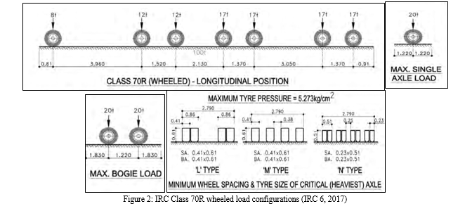
Figure 2 shows the IRC class 70R wheeled load configuration applied for the analysis of the bridge girders. The edge of the wheel loads is kept at 1.2m from the edge of the kerb for analyzing the bridge girders for these loads. The IRC 70R wheeled load configuration has 7 axle loads with loads ranging from 8 ton to 17 tons. A total of 100 tons of load is applied on the bridge over a length of 14.92m. The 70R also requires checks with localized heavier point loads using a 20 ton single axle load and a 40 ton tandem axle load with each axle of 20 ton.
For this bridge, even though there are only two lanes of traffic currently, there are 1.5m wide pedestrian footpaths at both ends of the deck. The total width of both footpaths is considered as one additional traffic lane, and the bridge is analyzed and designed for three lanes of traffic instead of two. This is done for two reasons; first there is a future potential for this bridge to be turned into a 3-lane vehicular bridge in the event of such demand. In such case, both footpaths can be converted into one additional vehicular lane without need for repair or retrofit of the bridge. Second, the IRC vehicular load intensity is much higher than pedestrian load, so the current 3-lane design is conservatively over designed for pedestrian loads.
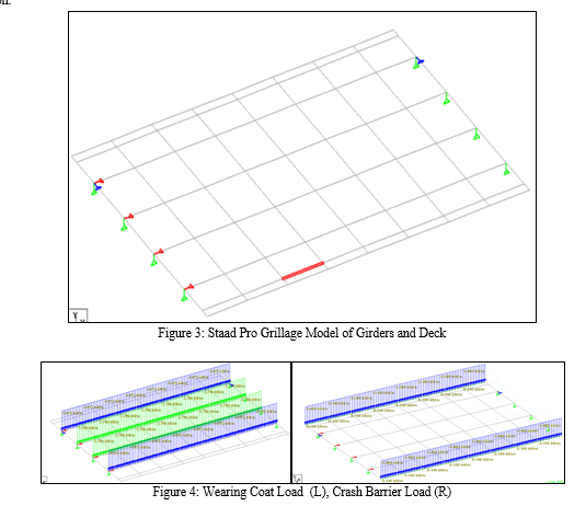
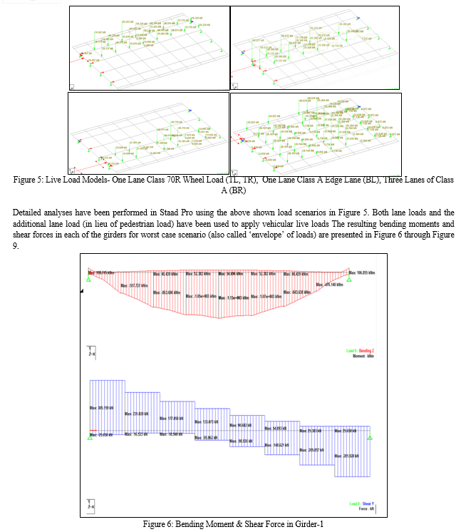
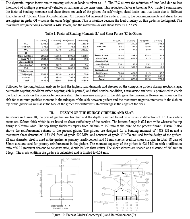
Grillage deck analysis has been performed to determine the moment and shear demands on girders and slab. Staad Pro software is used to perform this analysis. Figure 3 shows the grillage model of bridge slab and girders as modeled in Staad Pro. The Staad analysis showed that class 70R wheeled loads in 2 lanes and a single class A wheeled load in the 3rd lane created the maximum longitudinal flexural and shear demands on the girders whereas the class A eccentric lane load with just 150 mm clearance from the edge of the carriage way on the outer lane created maximum transverse flexural and shear demands in the slab. Within the slab, the Class 70R, 40 ton maximum bogie load created the maximum positive and negative flexure and shear forces in the transverse direction.

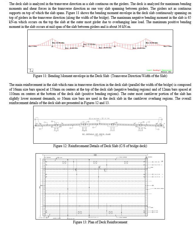
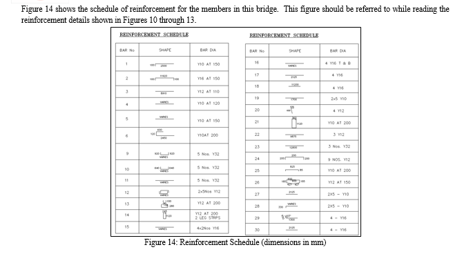
IV. ACKNOWLEDGEMENTS
The authors acknowledge the support of the Dean of the Student Affairs Dr. B Panduranga Rao, the Head of the Civil Engineering department and Professor Dr. Chava Srinivas and Visiting Professor Dr. Srimaruthi Jonnalagadda at VR Siddhartha Engineering College in Vijayawada
Conclusion
This paper presents the details of the analysis and design of the bridge to cross the premises of VR Siddhartha Engineering college in Kanuru mandal on the outer skirts of Vijayawada city. The paper presents the vehicular loads considered for the design of the bridge in accordance with the IRC specifications and the analyses performed in longitudinal and lateral direction in Staad Pro as well as using calculations in excel spreadsheets. The design and reinforcement details of the girders and the deck slab are presented. The bridge is designed for typical loads and typical methods. A missed opportunity is to design the girders as prestressed concrete members which would make the bridge more durable and reduce maintenance issues pertaining to cracking and spalling [18]. Similarly using Ultra-High-Performance concrete (UHPC) for bridge joints is another missed opportunity to improve durability of bridge joints and reduce maintenance costs [19]. These simple designs and material adaptations could have significantly enhanced the efficiency and performance of the bridge [20] and made it more robust while contributing to sustainable and resilient infrastructure practices [21].
References
[1] Gollapudi, P. R., Dendukuri, S. C.(2024). The Bridge Through The College (Part-1): Conception and Construction of Reinforced Concrete Bridge Across College Campus, International Journal of Scientific Research In Engineering and Management, IJSREM, 8(1), 1-11. [2] Jonnalagadda, S. & Vemuri, S. (2023a). Challenges in Traditonal Concrete Slab Construction for Housing Buildings in Developing Countries and Critical Need for Novel Methods. International Journal of Advances in Engineering and Management, 5(5), 176-186. [3] Jonnalagadda, S. & Vemuri, S. (2023b). Novel Methods and Materials for Concrete Floor Slab Construction for Small Family Housing Buildings in India. International Research Journal of Engineering and Technology, 10(7), 1048-1056. [4] IRC 5. (2015). Standard Specifications And Code Of Practice For Road Bridges, Section: I General Features of Design (Eighth Revision), Indian Roads Congress [5] IRC 6. (2017). Standard Specifications And Code Of Practice For Road Bridges, Section: II Loads And Load Combinations (Seventh Revision), Indian Roads Congress [6] IRC 22. (2015). Standard Specifications And Code Of Practice For Road Bridges, Section: VI Composite Construction (Limit States Design) (Third Revision), Indian Roads Congress [7] IRC 112. (2011).Code of Practice for Concrete Road Bridges, Indian Roads Congress [8] IRC SP:114. (2018).Guidelines for Seismic Design of Road Bridges, Indian Roads Congress [9] IS 456. (2000). Indian Standard Plain And Reinforced Concrete - Code Of Practice (Fourth Revision) Bureau of Indian Standards [10] IS 875. (2008). Code of Practice for Design Loads (Other Than Earthquake) For Buildings and Structures. Part 1: Dead Loads--Unit Weights of Building Materials and Stored Materials (Second Revision), Bureau of Indian Standards [11] IS 875. (2008). Code of Practice for Design Loads (Other Than Earthquake) For Buildings and Structures. Part 2: Imposed Loads (Second Revision), Bureau of Indian Standards [12] IS 1893. (2016). Criteria for Earthquake Resistant Design of Structures - Part 1 : General Provisions and Buildings, Bureau of Indian Standards [13] IS 1893. (2014). Criteria for Earthquake Resistant Design of Structures - Part 3: Bridges and Retaining Walls, Bureau of Indian Standards [14] Johnson, D. V. (2017). Essentials of bridge engineering. Oxford and IBH Publishing. [15] Vemuri, S. & Jonnalagadda, S. (2023c). Wind Analysis of Tall Buildings Using Codal Provisions, Stochastic Approach and CFD – A Comparative Study. International Journal of Advances in Engineering and Management, 5(7), 58-68. [16] Vemuri, S. & Jonnalagadda, S. (2023d). A Stochastic Approach to Determine Along-Wind Response of Tall Buildings. International Research Journal of Engineering and Technology, 10(7), 961-969. [17] Vemuri, S. & Jonnalagadda, S. (2023e). Analyses of Box Bridge and Comparison of Structural Behavior using 3D Finite Element and Typical 1D Line Models. International Journal for Research in Applied Science & Engineering Technology, 11(8), 488-497. [18] Jonnalagadda, S. & Vemuri, S. (2023f). Choosing Conventional Concrete, Ultra-High Performance Concrete or Steel as Material of Construction: An Opinion. European Modern Studies Journal, 7(4), 280-288. [19] Jonnalagadda, S., & Chava, S. (2023g). Ultra-High-Performance Concrete (UHPC): A state-of-the-art review of material behavior, structural applications and future. Electronic Journal of Structural Engineering, 25-30. [20] Jonnalagadda, S., Jonnalagadda, V., & Jonnalagadda, N. (2023h). The Adverse Impacts of Climate Change on Infrastructure and Proposed Adaptation Framework for Residential Structures: Part 1, European Modern Studies Journal, 7(5), 20-34 [21] Jonnalagadda, S. (2016). Artificial Neural Networks, Non Linear Auto Regression Networks (NARX) and Causal Loop Diagram Approaches for Modelling Bridge Infrastructure Conditions. All Dissertations, 1725. https://tigerprints.clemson.edu/all_dissertations/1725
Copyright
Copyright © 2024 Phani Ram Gollapudi, Satish Chandra Dendukuri. This is an open access article distributed under the Creative Commons Attribution License, which permits unrestricted use, distribution, and reproduction in any medium, provided the original work is properly cited.

Download Paper
Paper Id : IJRASET58761
Publish Date : 2024-03-03
ISSN : 2321-9653
Publisher Name : IJRASET
DOI Link : Click Here
 Submit Paper Online

