Ijraset Journal For Research in Applied Science and Engineering Technology
- Home / Ijraset
- On This Page
- Abstract
- Introduction
- Conclusion
- References
- Copyright
Structural Analysis & Effect of Impingement Cooling Flow in the Internal Surface on Temperature Distribution of a Vane in Gas Turbine Using Taguchi Technique
Authors: Shaheen Mahboob , D J Johnson, P. Gayatri
DOI Link: https://doi.org/10.22214/ijraset.2024.60775
Certificate: View Certificate
Abstract
Gas turbine always consider one of the most important systems in the modern engineering applications, because it has continuous ability to generate electric power. In gas turbines the major portion of performance dependency lies upon turbine blade design ,the blades are considered one of the important and expensive parts in the gas turbines , where the blades of first stage from failure .The blades of the gas turbine suffer from tensile stresses due to centrifugal forces resulting from the high rotational speed and because of the loading of dense gasses at a high temperature and speed ,as the centrifugal force is one of the problems that the designer of the turbine blades faces , as the designer aims to reduce stresses within the permissible limit. CFD study was carried out for evaluating the performance of a utility Steam Turbine. The flow in a turbine blade passage is complex and involves understanding of energy conversion in three dimensional geometries. The performance of turbine depends on efficient energy conversion and analyzing the flow path behavior in the various components of Steam Turbine. This study seeks the optimization of an axial turbine from a small gas turbine engine developed by ITA using Computational Fluid Dynamics (CFD) and Multi- Objective Optimization techniques focused on geometry changes to maximize the turbine performance. The simulation process will be done through the use of the commercial software SolidWorks.
Introduction
I. INTRODUCTION
The aeronautical industry and its competitiveness in the market of increasingly efficient aircraft, constantly seek through a lot of research and technological development, an increasingly safe and cheap solution to the final consumer who is the passenger. These surveys can follow different goals such as: drag reduction, lift improvement, fuel economy, noise reduction, improved thermal comfort, greater ease of manufacturing, robust parts design to increase your life, increased propulsion and reduced costs generally. For each of these fields, several studies were required. CFD allows observation of flow properties at locations which may not be accessible to (or harmful for) measuring instruments. For example, inside a combustion chamber, or between turbine blades. Designers and analysts can study prototypes numerically, and then test by experimentation only those which show promise. The aerodynamics of the flow in a turbine stage is rather complex and is still the subject of many ongoing research activities in the gas turbine community. The flow is inherently three dimensional due to the blade passage geometry with features such as twisting of the blade along the span, clearance between the blade tip and the shroud, film cooling holes and end wall contouring.
The Modern updates in computational techniques have given scope to understand the behavior of flow of fluid before the experimentation. Computational Fluid Dynamics (CFD) is one of the finest techniques to Check the behavior of flow over an object. Studies have proven CFD has given close results to experimental analysis [1,2]. Use of Navier stokes equation in CFD solving of the fluid Domains gives a better result with less error from the experimental analysis [3]. So, the study is conducted by modeling and simulation technique. The main factor that typically controls the performance of a gas turbine is the profile of the van. Several studies are been conducted to study the response of vane at different profiles. The chamber of vane plays a crucial role in selecting the profile. The increment in chamber shows a relative improvement in performance of the vane [4].
This is because the increment in chamber causes more pressure drop which leads to high drag force that helps in rotation [5]. Also, the position of maximum chamber plays a vital role in the performance of the vane. The position of maximum chamber at 30% of chord length have shown a dominant performance while studying the nature at a range of 10% to 60% [6].
The study on the SG 6043 and NACA 4412 is shown a dominant performance in SG 6043 over NACA 4412 in the enhancement of the aerodynamic characteristics [7]. The NACA 6409 has better fluid separation capacity which is proven from experimental results. But the NACA 4412 has dominated the results compared with NACA 6409[11, 27, 28]. The study on airfoil NACA 2412, NACA 4412 & NACA 6412 have proven that the profile of NACA 6412 has the superior flow separation over the remaining considered profiles [2,3]. The work is continued to NACA 6412, NACA 7412 & NACA 8412. The profile of NACA 8412 have the greater flow separation and lift-to-drag ratio [10,13]. The study of flow on RAE 2282, NACA 4415, NACA 4418 and NACA 6409 have shown that the RAE 2282 has best characteristics among the selected airfoils [29].
Coming to the material and coating of profile the material with high thermal conductivity should be considered [15,25]. The thermal study between the stainless steel and aluminum with epoxy coating. It shown that the stainless steel has shown better thermal characteristics [14]. The study of material is further continued between Inconel & titanium T6 [18], Titanium aluminum alloy [20] , 617Nickel & chromium steel[16], SS 304[17], Inconel 718 & N155[19] and EN 24, AISI 4130 & ZAMAK [21]. It is shown that the ZAMAK has best characters among all the materials studied above. Coming to coating material Y2O3 [11] and Zirconia [22] have shown that the zirconia is better suitable for coating.
The impingement holes are one of the best choices for cooling of gas turbine. The vane with 7,8,9,10,11 & 12 is arranged along the chord line. The vane with 8 holes on the chord line have shown better thermal distribution among the other configurations [20]. The leading-edge temperature and heat transfer analysis is carried out at 0, 5, 9 and 13 impingement holes. The vane with 13 holes has shown the minimum temperature at leading edge and optimum heat transfer [26]. The arrangement of the impingement also plays a viral role in heat transfer. The study of arrangement of inline and staggered holes. It is shown that 14 staggered holes have shown better heat transfer [23]. The density of coolant flowing through the impingement holes increases the efficiency of cooling [24].
II. METHODOLOGY
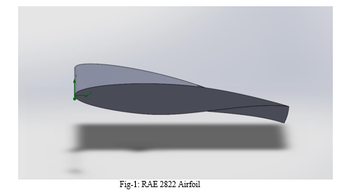
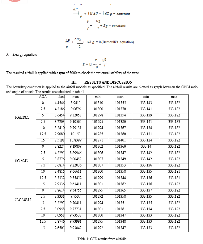
The gas turbine profile with RAE 2822, SG 6043 and NACA 8312 are studied. The chord of 300mm is selected. A 70-angle twist is applied for better improvement of lift [24]. The airfoils is applied with the inlet parameters of 8m/s at a temperature of 600C. Also, the surface roughness of profile is adjusted to 2 Micrometers. The airfoils are tested at 00–150- degree angle of attack at a interval of 2.50. The best airfoil is applied with the coolant flow of , 0.02, 0.03 Kg/s and the gas flow at temperature of 600C, 1200C & 1800C. The vane material of ZAMAK and coating of 0.1mm is applied with zirconia. The turbulence intensity of 2% is considered. Also it is assumed that the inlet gas has a inlet kinetic energy of 1 m2/S2 and specific depression of 1 S-1. These results are used for Taguchi optimization.

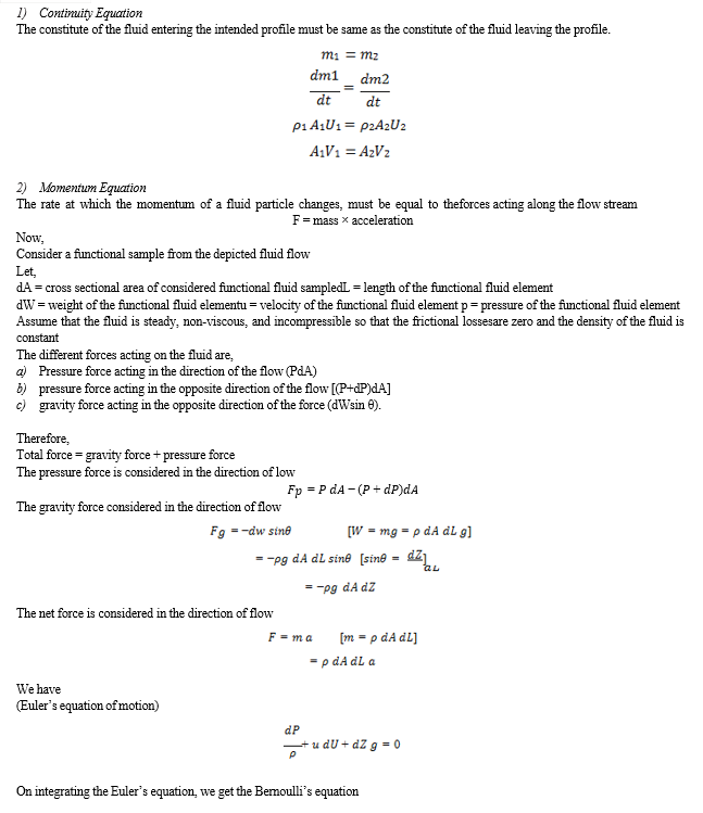
The geometries are applied with principles such as the continuity principle, Bernoulli’s principle and equations such as energy equation, kappa – epsilon equation. The calculation and evaluation are termed as follows:


Conclusion
The study is given various conclusions regarding flow separation and static strength of the body. Those are: 1) The RAE 2822 airfoil has better flow separation over SAE 6043 and NACA 8312. 2) Taguchi given a optimum operation range as 0.03 Kg/s of coolant inlet and 60 degree Celsius of gas inlet temperature. 3) RAE 2822 vane with 70 angle of twist has shown a good structural stiffness with stress as 3.996 e+08 N/m2 and strain as 4.015e-03. For future scope the profile can be further modified by means of dimples [13], etc gives a better result.
References
[1] Amaral LGF, Diaz, Tomita JT, et al. Optimization based on 3D CFD simulations of an axial turbine from a small gas turbine engine. Aeron Aero OpenAccess J. 2019;3(4): 198-211. [2] Scupi A., Dinu D.: Experimental and Numerical Methods for Hydrodynamics Profiles Calculation . TransNav, the International Journal on Marine Navigation and safety of Sea Transportation, Vol.5, No.4, pp.483-486,2011. [3] Tulus et al 2019 J. Phys.: Conf. Ser. 1376 012003 [4] Loya, A., Khan, M.Z.U., Bhutta, R.A. and Saeed, M. (2016) Dependency of Torque on Aerofoil camber Variation in Vertical Axis Wind Turbine. World Journal of Mechanics , 6, 472-486. [5] Zubin Zaheer et al 2019 J. Phys.: Conf. Ser. 1355 012006 [6] Jithendra Sai Raja Chada et al. Study of flow by varying the position of maximum chamber thickness on aerofoil. Technical Journal of Daukeyev University. 2021; 1(2): 69-75. [7] Aung, Y. Y. H., Soe, M. M., & Thu, A. M. (2016). Effect of Attack angle on Aerodynamics Analysis of Different Wind Turbine Wings using Numerical Simulation. American Scientific Research Journal for Engineering, Technology, and Sciences, 26(4), 319–329. [8] Abid, muhammad ali raza & Sarwar, M. & Tahir, Ahmad & Shah, Masood & Manzoor, S.. (2012). Gas turbine blade flow analysis comparison using CFD and Wind Tunnel. Proceedings of 2012 9th International Bhurban Conference on Applied Sciences and Technology, IBCAST 2012. [9] Singh A, Pujari AK, Prasad BVSSS. Conjugate heat transfer analysis of a rotor blade with coolant channels. Heat Transfer. 2021;1?31. [10] Geeri, Satish, Akhil Yuvaraj Manda, Jithendra Sai Raja Chada, and Sambhu Prasad Surapaneni. “Flow Behaviour on Aerofoils Using CFD.” Journal of Mechanical Engineering, Automation and Control Systems 1, no. 1 (June 30, 2020): 26–36. [11] Bathineedi Nagababu, V.S.Nagi Reddy, Abdul Arif et al. Design and cfd analysis on coated steam turbine blade. 2nd International conference on recent developments in science, humanities & management, 2018. [12] Rasal, S and Mr. Rohan R. Katwate. “Numerical Analysis of Lift & Drag Performance of NACA0012 Wind Turbine Aerofoil.” IRJET, 2017; 4(6): 2892-2896. [13] S. . Geeri, S. P. Surapaneni, J. S. R. Chada, and A. Y. Manda, “Studies Based on CFD Behaviour of Aerofoil and Regression Analysis”, Engineering Science & Technology, vol. 3, no. 1, pp. 55–68, [14] Oct. 2021 [15] Hao, J., Zhang, M. & Huang, X. Experimental Study on Influences of Surface Materials on Cavitation Flow Around Hydrofoils. Chin. J. Mech. Eng. 32, 45 (2019). [16] Rao, Nageswara. 2011. ‘Materials for Gas Turbines – An Overview’. Advances in Gas Turbine Technology. InTech. [17] [16] B.Sai Venkata Krishna, .Chakradhar Goud et al. CFD And Heat Transfer Analysis Of Air Craft Gas Turbine Blade, IJRAT 2019. [18] Kukutla, P.R., Prasad, B.V.S.S.S. Secondary flow visualization on stagnation row of a combined impingement and film cooled high-pressure gas turbine nozzle guide vane using PIV technique. J Vis 20, 817–832 (2017). [19] Theju V, Uday P S, PLV Gopinath Reddy, C.J.Manjunath et al. Design and Analysis of Gas Turbine Blade. IJIRSET, 3(6): 2014. [20] R D V Prasad1, G Narasa Raju2, M S SSrinivasa Rao3, N Vasudeva Rao. Steady State Thermal & Structural Analysis Of Gas Turbine Blade Cooling System. IJERT; 2(1): 2013. [21] Deepanraj, B., & Lawrence, P. (2011). Theoretical Analysis of Gas Turbine Blades by Finite Element Method. Journal of the Institute of Engineering, 8(1-2), 1–11. [22] G Nagendra Krishna, K.Rajesh, A.Swarna Kumari et al. Design and analysis of steam turbine blade and shaft assembly. IJRI; 2(4): 2015. [23] Leandro Augusto de Souza, Elisângela Martins Leal, Adilson Rodrigues da Costa & Milton Sergio Ernandes d Lima et al. Global Journal of Researches in Engineering ( A ) Volume XIxX Issue III Version I, 2019. [24] Priyanka Singh, O P Shukla et al. Heat Transfer Analysis of Gas Turbine Rotor Blade Through Staggered Holes Using CFD. International Journal of Engineering Research and General Science. 4(2),2016. [25] Sahu, M., Shaik, M. (2022). \'Numerical investigation on cooling performance of a twisted gas turbine blade with leading edge cooling holes\', Journal of Computational & Applied Research in Mechanical Engineering (JCARME), 11(2), pp. 397-407. [26] Pujari, A., Prasad, B. and Sitaram, N. (2021) Effect of Thermal Conductivity on Nozzle Guide Vane Internal Surface Temperature Distribution . International Journal of Turbo & Jet-Engines, Vol. 38 (Issue 2), pp. 135-151. [27] K Hari Brahmaiah , M.Lava Kumar at al. (2014) Heat Transfer Analysis of Gas Turbine Blade Through Cooling Holes. International Journal of Computational Engineering Research, 4(7). [28] Nirav Prajapati, Umang Patdiwala, Piyushkumar Surani et al .,Experimental Validation Of Naca 6409 Airfoil Using Cfd Analysis. JETIR 8(4). 2021. [29] MD. Safayet Hossain, Muhammad Ferdous Raiyan, Mohammed Nasir Uddin Akanda, Nahed Hassan Jony. A comparative flow analysis of NACA 6409 and NACA 4412 aerofoil. International Journal of Research in Engineering and Technology. 3(10). 2014. [30] Kushal Gendcha1 Kalpit P. Kaurase, Analysis of Transonic Flow over Airfoil using CFD for Gas Turbine Blades. International Journal for Scientific Research & Development. 4(5). 2016. [31] Yixuan Xia, Analysis of the research status of stationary gas turbine and its material selection. Proceedings of the 3rd International Conference on Signal Processing and Machine Learning. (2023). [32] Mohammed Talal Mohammed, Ziad Shakeeb Al Sarraf and Sabah Mohammed Jamil. Finite Element Simulation and Stress Analysis of Gas Turbine Blade Due to Centrifugal Force. International Journal of Advanced Natural Sciences and Engineering Researches. 7(6). 2023.
Copyright
Copyright © 2024 Shaheen Mahboob , D J Johnson, P. Gayatri. This is an open access article distributed under the Creative Commons Attribution License, which permits unrestricted use, distribution, and reproduction in any medium, provided the original work is properly cited.

Download Paper
Paper Id : IJRASET60775
Publish Date : 2024-04-22
ISSN : 2321-9653
Publisher Name : IJRASET
DOI Link : Click Here
 Submit Paper Online

