Ijraset Journal For Research in Applied Science and Engineering Technology
- Home / Ijraset
- On This Page
- Abstract
- Introduction
- Conclusion
- References
- Copyright
Thermo Hydraulic Analysis of a Heat Pipe Using ANSYS Fluent
Authors: Mohammad Azam, S. Venkateswara Rao, K. Prasada Rao
DOI Link: https://doi.org/10.22214/ijraset.2024.63899
Certificate: View Certificate
Abstract
Miniaturization, Integration of functionality and speed increase are recognized as business drivers in electronics industry today. The aspects increase power dissipation, high temperatures and affects reducing sizes because of limitations in cooling techniques. Heat pipes come handy in these situations as they operate with highest heat conductance compared to any other mode of heat transfer and available over wide range of parameters. It consists of an evaporative section, adiabatic section, and condensing section. The working fluids generally used are water, ethanol, acetone, sodium, and mercury. Various applications include heat exchanges in electrical and electronic equipment, air-conditioners, refrigerators, heat exchangers, transistors, capacitors, ovens, furnaces, production tools, transportation etc. Heat pipes are also used in laptops to reduce the working temperature for better efficiency. Their application in the field of cryogenics is very significant, especially in the development of space technology. In this work, the effect of heat pipe process parameters i.e. mass flow rate of cooling medium (water), inclination angle and heat input on the thermal performance of thermosyphon and Sintered copper wick heat pipe were studied Numerically by using ANSYS FLUENT.
Introduction
I. INTRODUCTION
Heat pipe is a heat transfer device which can transport large quantities of heat through a small cross - sectional area over a considerable distance with no additional power input to the system. It can combine the principles of both thermal conductivity and phase transition to efficiently manage the transfer of heat between two solid interfaces. Due to the very high heat transfer coefficients for boiling and condensation, heat pipes are highly effective thermal conductors. Furthermore, design and manufacturing simplicity, small end to end temperature drops, and the ability to control and transport high heat rates at various temperature levels are unique features of heat pipes.
A. Historical Development
The predecessor of the heat pipe, the Perkins tube, was introduced by the Perkins family from mid-nineteenth to the twentieth century through a series of patents in the United Kingdom. Most of the Perkins tubes were wickless gravity- assisted heat pipes (Thermosyphon), in which heat transfer was achieved by change of phase. The Perkins tube design closest to the present heat pipe was patented by Jacob Perkins (1836).
The introduction of the heat pipe was first conceived by Gaugler (1944) [3]. In 1962, Trefethen resurrected the idea of a heat pipe in connection with the space program. Later Grover et.al (1964) [6] and Grover (1966) [10] built several prototype heat pipes, the first of which used as a working fluid and was soon followed by a sodium heat pipe which operated at 1100 K.
Grover gave a very limited theoretical analysis on heat pipes, but presented experimental results obtained from stainless steel heat pipes incorporating a screen wick with sodium, silver and lithium as working fluids.
In 1964, RCA (Radio Corporation of America) was the first commercial organization to perform heat pipe research. Heat pipes were constructed using copper, nickel; stainless steel, molybdenum and TZM molybdenum containers, and working fluids such as water, cesium, sodium, lithium and bismuth were used.
The recognition of the heat pipe as a reliable thermal device was initially due to the preliminary theoretical results and design tools that were reported in the first publication on heat pipe analysis by Cotter (1965).
The components of a heat pipe are a sealed container (pipe wall and end caps), a wick structure, and a small amount of working fluid which is in equilibrium with its own vapor. The length of a heat pipe is divided into three parts: evaporator section, adiabatic (transport) section and condenser section.
A heat pipe may have multiple heat sources or sinks with or without adiabatic sections depending on specific applications and design. Heat supplied to the evaporator section by an external source is conducted through the pipe wall and wick structure, where it vaporizes the working fluid. The resulting vapor pressure drives the vapor through the adiabatic section to the condenser, where the vapor condenses, releasing its latent heat of vaporization to the provided heat sink as shown in the Figure 1.1.
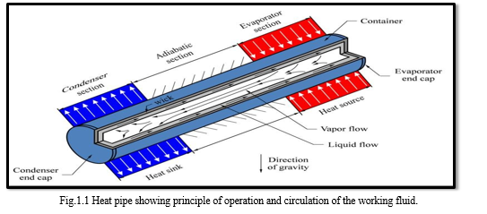
The capillary pressure created by the menisci in the wick pumps, the condensed fluid back to the evaporator section. Therefore, the heat pipe can continuously transport the latent heat of vaporization from the evaporator to the condenser section. This process will continue as long as there is a sufficient capillary pressure to drive the condensate back to the evaporator.
A capillary pressure exists at the liquid-vapor interface due to the surface tension of the working fluid and the curved structure of the interface. The difference in the curvature of the menisci along the liquid-vapor interface causes the capillary pressure to change along the heat pipe. This capillary pressure gradient circulates the fluid against the liquid and vapor pressure losses, and adverse body forces such as gravity. The vapor pressure changes along the heat pipe due to friction, inertia and blowing (evaporation) and suction (condensation) effects, while the liquid pressure changes mainly as a result of friction.
Yanxi Song et.al [1] measured the chaotic way of behaving of closed loop oscillating heat pipe or pulsating heat pipes (PHPs). The PHPs were manufactured by capillary vessel with outer diameter of 2.0mm and inner diameter of 1.20mm. FC-72 (C6F14, perfluoro hexane) and deionised water were used as the fluent. They conducted the investigation by keeping number of turns as 4, 6 and 9 and inclination angle from 5? to 90?, mass-charge ratios between 50% and 80% and calorific value from 7W to 60W. The outcomes showed that at lower inclination angles, interrelated dimensions are not proportionate at distinct turns of PHP’s. The non-proportionality of interrelation dimensions is remarkably upgraded with increase in the inclination angle. The maximum mass-charge ratio is about 60–70%. The more the heating power, greater is the Kolmogorov entropies and correlation dimensions. For almost runs, Kolmogorov entropies and large correlation dimensions resemble to lower thermal resistances, i.e., finer thermal performance, apart from FC-72 PHPs at minor inclination angle of θ<15°.
Sameer Khandekar et.al [2] reported that a pulsating heat pipe exhibits numerous functioning quasi-steady states when the working and limiting conditions are maintained stable in their study. Continuous online measures of temperature and static pressure at key places, as well as flow simulation, have been recorded for even more than twelve hours each experimental session of fabrication for a defined heat load level and volume filling ratio. Four different quasi-steady states have been seen. The distinct characteristic two-phase fluid flow and accompanying efficient device conductivity that define each quasi- steady phase show the robust thermo-hydrodynamic connection that controls the thermal efficiency. Continuous linear flow rotations make up the quasi- steady phase with the highest thermal performance, whereas the state with poor thermal efficiency is defined by the periodic setbacks in the stream in both directions. In order to contrast the optimal thermal effectiveness of a flat thermal pipe-thermal component application in an increased VGA card air conditioning system with a conventional copper metal sheet embedded with three 6 mm diameter heat exchanger module under 3 different angles of 0°, 90°, and 180°. Jung-Chang Wang [3] researched the 3-D experimental and numerical methods. The straight heat exchanger module seems to have the highest thermal performance at a high GPU power of 180 W and 180° of inclination, according to the results. Around 5%, simulated results and observational results are all in excellent accordance.
II. NUMERICAL STUDIES ON THERMOSYPHON HEAT PIPE
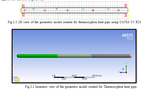
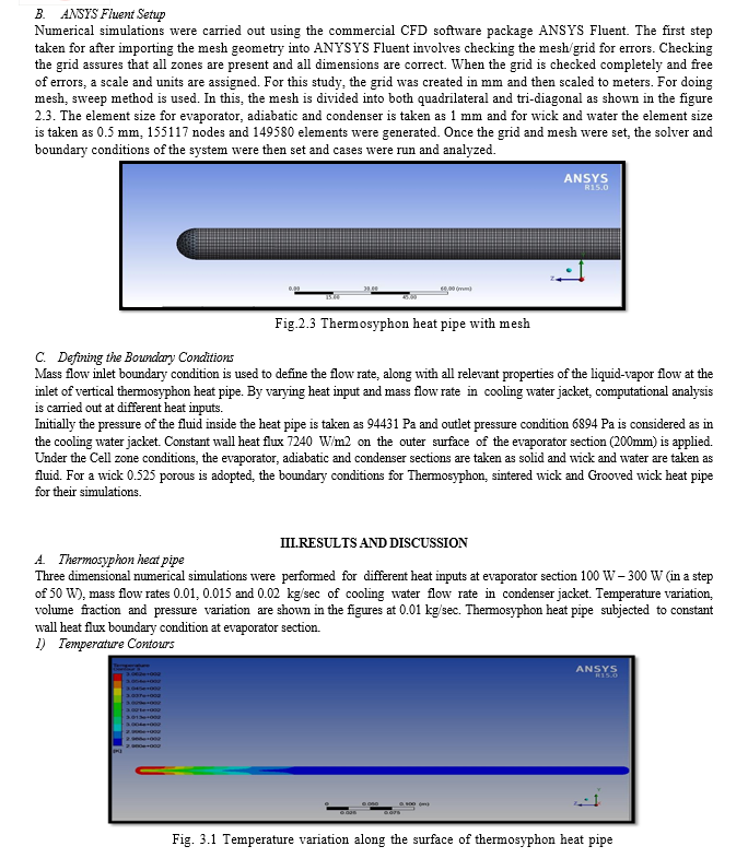
Computational analysis is used to estimate the heat transfer coefficient and thermal resistance characteristics of working fluid i.e. water flowing through a vertical circular thermosyphon heat pipe. The vertical thermosyphon is modeled and meshed by using CATIA V5 R21 software; geometry of the heat pipe is created in and imported flow problem is analyzed by ANSYS fluent database. The dimensions are, inner diameter of 14.0 mm, length 565 mm, tube material is copper, working fluid is water. Inlet (evaporator) boundary condition as heat flux, mass flow rate in the condenser region and outlet temperature boundary condition are used to simulate the heat transfer coefficient and thermal resistance of working fluid at different heat inputs and cooling fluid variation in the condenser jacket.
The basic procedural steps to obtain CFD simulated results are shown below.
- Creating the model geometry and mesh using CATIA V5 R21.
- Start the appropriate solver for 2D or 3D modeling in ANSYS Fluent.
- Import the grid into ANSYS Fluent.
- Check the grid.
- Select the solver formulation.
- Choose the basic equations to be solved.
- Specification of material properties.
- Specification of boundary conditions
- Adjusting the solution control parameters.
- Initializing the flow field.
- Start run in solver.
- Examining the results.
- Saving the results.
A. CFD Analysis for Thermosyphon
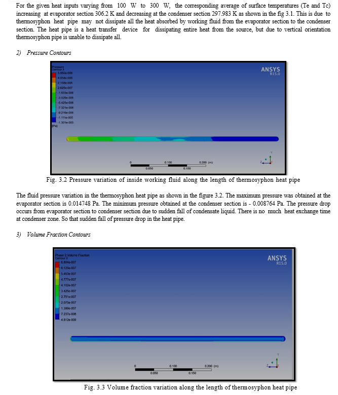
2D and isometric view of geometric model created for thermosyphon heat pipe using CATIA V5 R21 are shown in the figures 2.1 and 2.2 respectively.
Conclusion
In this work numerical investigations of the effect of heat pipe process parameters such as coolant mass flow rate (m), Orientation and heat input (Q) to the Thermosyphon and sintered wick heat pipe was examined. According to the numerical results, when the heat input (Q) and mass flow rate (m) of the coolant increase, the thermal resistance (Rth) decreases from 0.0709 to 0.02057 K/W and the heat transfer coefficient and the heat transfer coefficient Continuously increases 1413.50 to 4872.65 W/m2 K, which signifying an improvement in thermal performance of heat pipe. For different heat inputs conditions, the temperature, velocity, and volume of fraction contours are analyzed and discussed. It was found that when heat input increases, the heat transfer coefficient rises while thermal resistance was decreased.
References
[1] Yanxi Song, Jinliang Xu, “Chaotic behavior of pulsating heat pipes”, International Journal of Heat and Mass Transfer, 2009, Vol.52, Pp: 2932-2941. [2] Sameer Khandekar, Anant Prasad Gautam, Pavan K. Sharma, “Multiple quasi-steady states in a closed loop pulsating heat pipe”, 2009, International Journal of Thermal Sciences, Vol.48, Pp:535-546. [3] Jung-Chang Wang, “3-D numerical and experimental models for flat and embedded heat pipes applied in high-end VGA card cooling system”, International Communications in Heat and Mass Transfer, 2012, Vol.39, Pp: 1360-1366. [4] Chao-Chi Shih, Chih-Chieh Chen, Chih-Chung Chang, Sih-Li Chen, “Dynamic test strategy for diagnosing a heat pipe cooling module”, International Communications in Heat and Mass Transfer, 2012, Vol.39, Pp:1360-1366. [5] Dehao Xu, Taofei Chen, Yimin Xuan, “Thermo-hydrodynamics analysis of vapor–liquid two-phase flow in the flat-plate pulsating heat pipe”, International Communications in Heat and Mass Transfer, 2012, Vol.39, Pp: 504-508. [6] Jian Qu, Huiying Wu, Ping Cheng, “Start-up, heat transfer and flow characteristics of silicon- based micro pulsating heat pipes”, International Journal of Heat and Mass Transfer, 2012, Vol.55, 6109-6120. [7] Yi- Hsuan, Tun-Ping Teng, Bo-Gu Lin, “Evaluation of the thermal performance of a heat pipe using alumina nano-fluids”, Experimental Thermal and Fluid Science, 2012, Vol. 44, Pp:504-511. [8] Chih-Yung Tseng, Kai-Shing Yang, Kuo-Hsiang Chien, Ming-Shan Jeng, Chi-Chuan Wang, “Investigation of the performance of pulsating heat pipe subject to uniform/alternating tube diameters”, Experimental Thermal and Fluid Science,2013, Vol.54, Pp:85-92. [9] Mauro Mamelia, Vincenzo Manno, Sauro Filippeschi, Marco Marengo, “Thermal instability of a Closed Loop Pulsating Heat Pipe: Combined effect of orientation and filling ratio”, Experimental Thermal and Fluid Science, 2014, Vol.55, Pp: 302-309. [10] Yanxin Hu, Tengqing Liu, Xuan you Li, Shuang feng Wang, “Heat transfer enhancement of micro- oscillating heat pipes with self-rewetting fluid”, International Journal of Heat and Mass Transfer,2013, Vol.70, 496-503. [11] Jung-Shun Chen, Jung-Hua Chou, “Cooling performance of flat plate heat pipes with different liquid filling ratios”, International Journal of Heat and Mass Transfer, 2014, Vol.77, Pp: 874-882. [12] Xiao Lu, Jin-Jia Wei, “Experimental study on a novel loop heat pipe with both flat evaporator and boiling pool”, International Journal of Heat and Mass Transfer, 2014, Vol. 79, Pp:55-63. [13] Hassam Nasarullah Chaudhary, Ben Richard Hughes, “Analysis of the thermal cooling capacity of heat pipes under a low Reynolds number flow”, Applied Thermal Engineering, 2014, Vol. 71, Pp:559-572. [14] Eric A. Silk, David Myre, “Fractal Loop Heat Pipe performance testing with a compressed carbon foam wick structure”, Applied Thermal Engineering, 2013, Vol. 39, Pp: 290-297. [15] Wang wen, ZhuanRui, “Simulation of Two-Phase Flow in U Type Heat Pipes”, International Heat Pipe Symposium, 2011, Vol. 11, Pp: 249-255. [16] M.K. Russel, C. Young, J.S. Cotton, C.Y. Ching, the effect of orientation on U-shaped grooved and sintered wick heat pipes,Applied Thermal Engineering , 2011, Volume 31, Pp:69-76. [17] Milad Tajik Jamal-Abad, Amirhossein Zamzamian, Maziar Dehghan, Experimental studies on the heat transfer and pressure drop characteristics of Cu–water and Al–water nanofluids in a spiral coil, Experimental Thermal and fluid science, 2013, Volume 47, Pp: 206-212. [18] Souad Harmand, Raymond Sonan, Michel Fakès, Hamdy Hassan,2011, Transient cooling of electronic components by flat heat pipes, Applied thermal engineering, Volume 31, Pp: 1877- 1885. [19] Yong Ji*, Heng-fei He, Zhi-xin Zeng, 2013, Evaporation and condensation heat transfer in a heat pipe with a sintered-grooved composite wick, Applied thermal Engineering, Volume 50, Pp: 342- 351. [20] Yew Mun Hung, Kek-Kiong Tio, 2012, Thermal Analysis of a Water-Filled Micro Heat Pipe with Phase-Change Interfacial Resistance, ASME Journal of Heat transfer, Volume 134, Pp:112901 (11 pages). [21] S. Lin, P.A. Kew, K. Cornwell, 2001, Two-phase heat transfer to a refrigerant in a 1 mm diameter tube, International Journal of Refrigeration, Volume 24, Pp:51-56. [22] J. Padhye, V. Firoiu, and D. Towsley, “A stochastic model of TCP Reno congestion avoidance and control,” Univ. of Massachusetts, Amherst, MA, CMPSCI Tech. Rep. 99-02, 1999. [23] Wireless LAN Medium Access Control (MAC) and Physical Layer (PHY) Specification, IEEE Std. 802.11, 1997.
Copyright
Copyright © 2024 Mohammad Azam, S. Venkateswara Rao, K. Prasada Rao. This is an open access article distributed under the Creative Commons Attribution License, which permits unrestricted use, distribution, and reproduction in any medium, provided the original work is properly cited.

Download Paper
Paper Id : IJRASET63899
Publish Date : 2024-08-07
ISSN : 2321-9653
Publisher Name : IJRASET
DOI Link : Click Here
 Submit Paper Online

