Ijraset Journal For Research in Applied Science and Engineering Technology
- Home / Ijraset
- On This Page
- Abstract
- Introduction
- Conclusion
- References
- Copyright
Vibration Analysis of Engine Mounting Bracket of a Car using Experimental and FEA
Authors: Abhinav Shelar, Atul Aradhye, Prashant Mali
DOI Link: https://doi.org/10.22214/ijraset.2023.51534
Certificate: View Certificate
Abstract
Overall, the research presented in this dissertation focused on the optimization of the tie rod of a steering system of a car using experimental and FEA analysis. The tie rod was traditionally made of cast iron, but in this study, an aluminum material was used. The results of the theoretical, experimental, and FEA analysis were compared to the conventionally used tie rod material in terms of cost and weight optimization. The study found that the use of aluminum material for the tie rod resulted in a reduction in weight and cost without compromising on the functional strength of the tie rod. Additionally, the research also discussed the importance of regular maintenance and inspection of the steering system and suspension, as well as the potential failure modes of the tie rod and their causes.
Introduction
I. INTRODUCTION
The most important vibration relevant excitations in a car engine can be identified as follows: combustion force, main bearing reaction forces, piston side forces and valve train forces. The development of engine bracket can make the engine capable of absorbing vibration. Automotive engine mounting system must satisfy the primary tasks such as engine movement, engine rigid-body dynamic behavior, and vibration isolation. The design and development of mounting bracket through use of computer-aided engineering (CAE) tools such as ANSYS can achieve the requirements for mounting system. A good mounting system separates engine input vibration from the vehicle body and suppress the effect of road inputs to the vehicle driver. Optimizing the mounts system in early stages of engine design is possible by implementation of CAE tools. CAE results can be analyzed without any costly prototypes [1].
It is important to conduct Finite Element Analysis (FEA) of the engine bracket to understand the structural characteristics and dynamic behavior of the bracket. Different materials, such as Gray Cast Iron and Aluminium alloy, can be studied and compared through FEA to determine the best material for the bracket. The results of the FEA can be validated through experimental testing to ensure the accuracy of the analysis. Additionally, by using CAE tools such as Ansys, the engine bracket can be optimized in the early stages of engine design, reducing the need for costly prototypes. This allows for efficient and effective design and development of the engine bracket system [3].
- Location of Bracket Iinstallation: The engine mount assembly includes a support member that is attached to a vehicle frame component, two elastomeric engine isolators positioned on the support member, and two engine mounting brackets. The bracket design is optimized for stiffness, strength and mass, while still allowing for a shortened development cycle. The limited vertical space for the rubber mount and bracket limits the ability for maximum isolation of vibration. The bracket also supports the support member on the engine and prevents the engine from moving rearward in the event of a frontal collision. The bush is engaged with cut-out portions on the bracket's supporting arm portions.

II. LITERATURE REVIEW
Zhang Junhong et al. [1] have investigated the vibratory and acoustic behaviour of the internal combustion engine, which is a highly complex system composed of many components subjected to loads of varying magnitude and operating at a wide range of speeds. CAE tool development will result in a significant reduction in engine development time while also ensuring a dramatic increase in product quality. CAE capabilities in engine dynamic and acoustic behaviour simulation and focuses on the relative merits of modification and full-scale structural/acoustic optimisation of engine, as well as the creation of new low-noise designs. Modern CAE tools enable engine analysis, evaluation, and acoustic optimisation.
Gabriel-Petru ANTON et al.[2] have investigated the NVH test-calculation correlation, engine finite element (FE) model updating, and engine/body interface point vibration level (low and medium frequency range). The main goal of this approach is to use an updated FE model to obtain the absolute values of the vibration level (low and medium frequency range) on the interface points. The experimental and theoretical analyses used in this work enabled us to understand the true vibratory behaviour and obtain a new FE model that is more closely related to reality. The final updating, the test-calculation correlation results, and the operational simulation are all included.
Senthilnathan Subbiah et al. [3] have developed durability tests on vehicles in the end-user environment to reduce failures and warranty costs in the end-user hands. Failure analysis of three-wheeler vehicle muffler mounting brackets observed during the durability test. At a distance of 10,000 km, all of the vehicles had cracks at the weld location between the engine cradle and brackets. The fishbone diagram is used to identify many possible causes of failures. The design was further investigated using the finite element method (FEM). For the engine cradle assembly, a FEM model was created in which the engine and muffler were modelled as point masses. The results show that the weld location has a high magnitude of stresses and strain energy. According to the design, the bracket was mounted on the engine cradle as a cantilever beam with one-plane welding. Although the modified design eliminated the above failure, it shifted the failure mode to the bush-bracket region.
Youngwoo Choia et al. [4] By extending the 160,000 km, the measured acceleration signals are analysed for virtual damage and frequencies. The acceleration test of six degrees of freedom (DOF) in the time domain using MAST and the acceleration test of single-DOF in the frequency domain using single axis equipment are performed for the accelerated vibration test. The measured PG acceleration signals, which are the same as the virtual damage of 160,000 km, are used for the accelerated six-DOF test. For the single-DOF test, the axis displaying the maximum virtual damage value from the real road test is used. After analysing frequencies, the tests are carried out by enveloping and amplifying PSD lines from real roads. The six-DOF acceleration tests reveal no failures. However, the connection between the battery and the bracket had been broken in single-DOF tests. It is for this reason that the chosen test axis has the highest virtual damage values when analysing real roads. The results are satisfactory in terms of safety, but further research will improve optimisation.
S.K. Loh et al. [5] has discussed some Finite Element (FE) analyses performed, such as frequency analysis, to determine the structural response due to harmonic excitation over a frequency range. Based on the frequency domain responses, the resonant frequency can be predicted. Furthermore, the static and dynamic vibration analyses provide the maximum structural stress condition under static and dynamic loading. The predicted maximum stresses are compared to the inherent yield strength of the material. The study does not address plastic deformation because only elastic properties are defined. A fatigue failure prediction of the current P-TAC motor bracket was also investigated using FE simulation and a fatigue failure criteria approach. To predict the possibility of fatigue occurrence, the dynamic stress curve with mean stress and alternating stress has been applied in established fatigue failure criteria such as Yield Criteria and Fracture Criteria. This method is regarded as a conservative prediction method for preventing structural fatigue, and it is best suited and safe for certain design applications. Different modifications of the motor bracket geometry have been investigated in an effort to strengthen the motor bracket, and the results of each analysis are compared. The rib support, edge radius, and thickness have all been changed and added to see what effect they have on the overall static and dynamic behaviour. Based on the analyses, it is discovered that adding rib-supports and increasing edge radius can significantly improve structural performance.
S. Irving et al. [6] has studied the fatigue performance of two different bracket connections intended for use in high-speed ocean craft. Weld quality within the curved or nested insert has a profound effect on fatigue behaviour, according to constant amplitude, cyclic tests. Under extreme conditions, the loss in fatigue performance caused by poor weld quality may outweigh the benefit obtained by more optimal bracket designs. When a good quality butt weld with deep penetration is used, the nested bracket outperforms the traditional soft toe bracket in terms of fatigue performance.
Mehmet Firat et al. [7] It was determined that the proposed solution is based on explicit, incremental, and implicit iterative finite element approaches for numerical simulation of stamping operations.
Factor analysis is used to evaluate the influence of the numerical model parameters, and response surfaces produced by multi-linear regression are used to describe them. The proposed methodology is applied to a forming procedure that results in spring back-critic channel geometry. To create a numerically calibrated simulation model, the influences of the punch velocity and element size are evaluated along with the effects of the modelling parameters. Comparisons with experimental data showed that the suggested approach worked well for spring back predictions. The engine suspension bracket is made of high-strength steel, and the proposed technique is used in the stamping examination of the bracket.
III. EXPERIMENTAL ANALYSIS
A. Impact Testing Necessities
To obtain accurate results in impact testing, there are certain points that need to be considered. These include the ability to approve or decline, a pretrigger delay, exponential windowing, and the force measurement.
B. Pre-Trigger Delay
Additionally, two time domain windows, such as force and exponential windows, are employed in impact testing. These windows are applied to the signals after they have been sampled by the FFT analyzer. The force window helps to eliminate noise from the impulses (or force) signal, while the exponential window reduces spectrum response leakage in the impulse response signal. This is crucial for obtaining accurate results in impact testing.
C. Force & Exponential Windows
Additionally, it is important to consider the use of a pretrigger delay to ensure that the entire impact signal is captured, and the use of approve/decline capabilities to filter out any unwanted signals. Overall, proper consideration and use of these techniques can lead to more accurate results in impact testing.
D. Leakage
The transform window makes the assumption that the signal being changed is periodic in nature. The pulse would have to have continuities now at start and finish when replayed just outside of the transformed screen to be deemed periodic in the transform window. Signals in the transform window that are deemed periodic are:
-
Signals that are totally confined inside the transformed frame.
- Cyclic signals that finish an exact number of times inside the transformation frame. However, if the temporal signal is not regular in the transformation frame, it will widen its spectrum when translated to the frequency domain, a phenomenon known as leakage. Leakage alters the spectral range and can cause incorrect findings. As a result, if a impact test signal response amplitude decreases to zero (or almost zero) well before expiry of the test windows, there is zero leaking and no extra windowing is required. If, on the other hand, the reaction doesn't really decrease to nil well before completion of a sampling window, a logarithmic screen should be employed to reduce the impacts of leakage in the structural response. The exponentially frame consistently increases simulated damper for each of the structure's modes. After curve fitting, this synthetic damp is eliminated from the modal damp estimates. Most crucially, a well fitted exponentially frame will completely confine the original signal inside the sampling window, reducing leakage to the minimal inside its range.
E. Accept/Reject
Because accurate impact testing results depend on understanding the factors that affect them, frequency response function (FRF) measurements are typically performed using spectrum averaging, a feature found in most modern FFT analyzers. It is recommended to use 3 to 5 impacts per computation when evaluating FRFs. An FFT analyzer designed for impact testing should have the capability to accept or reject the results of individual impacts, as some impacts during the measurement process may not be accurate. The ability to accept or reject impacts saves time and allows for efficient data collection during impact testing.
F. Roving Hammer Test
In a roving hammer test, a hammer is used to strike the structure at different locations, known as the degrees of freedom (DOFs). The impact location is changed for each measurement, and an accelerometer is placed at a fixed location to measure the response. The measured frequency response functions (FRFs) are used to determine the mode shapes of the structure, and multiple impacts are used to improve the accuracy of the results.
A 2-channel FFT analyzer is used to calculate the FRFs between the impact location and the fixed response location. The setup for this test typically includes the hammer and accelerometer, as well as the necessary data acquisition equipment to collect and analyze the results.
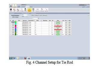
G. Roving Tri-axial Accelerometer Test
With a roving tri-axial accelerometer, all the points on the structure can be impacted in all three directions, allowing for more accurate and complete characterization of the structure's mode shapes. However, this method requires a 4-channel FFT analyzer for simultaneous sampling of the tri-axial accelerometer and force data, which may be more expensive than a 2-channel analyzer. Additionally, the stationary impact point may be less representative of the structure's overall response when compared to a roving hammer test.
IV. EXPERIMENTAL ANALYSIS OF TIE ROD USING FFT ANALYZER
A. Experimental setup
- The Fast Fourier Transform (FFT) Analyzer: The FFT spectrum analyzer allows you to visualize the frequency content of a signal and identify any harmonic or noise components that may be present. It is commonly used in a variety of applications such as vibration analysis, audio and speech processing, and communication systems. The FFT analyzer can provide detailed information about the frequency components of a signal and can be used to identify and troubleshoot issues with the system under test.
- Experimental Set Up: The experimental set up for engine bracket is as shown in figure.
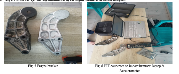
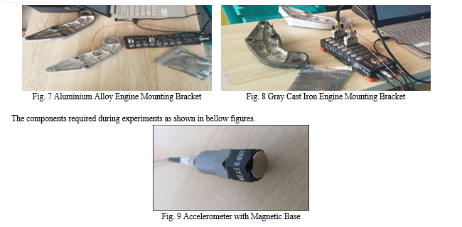
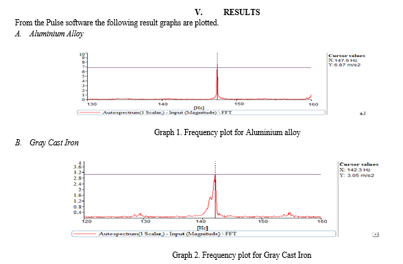
The Bracket one end is fixed to the frame and other end having three holes is connected to Exciter. Then magnetic based Accelerometer is connected to first port of FFT and mounted on Engine Bracket. With the help of Exciter Controller excitation given to Bracket. This excitation is measured by FFT and converts it in to frequency. FFT is connected to computer. Frequency send by FFT is read in computer with the help of software ‘Pulse’ and graphs are plotted. This shows the required results.
VI. FINITE ELEMENT ANALYSIS
The finite element method (FEM) is a numerical technique for solving partial differential equations that describe the behavior of a physical system. It is a powerful tool for analyzing complex engineering structures and systems, such as automotive engine brackets, because it can handle large amounts of data, model complex geometries and materials, and simulate real-world loading and boundary conditions. FEM allows engineers to predict the behavior of a structure under different loading conditions, identify critical areas of stress, and optimize the design for better performance and safety. Additionally, FEM can be used to simulate the effects of aging and fatigue on a structure, helping to ensure its longevity and reliability. Overall, FEM is a valuable tool for engineers in the automotive industry, as it helps to improve the design, safety, and performance of engine bracket systems.
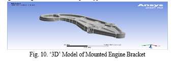
‘3-D’ MODEL OF ENGINE MOUNTING BRACKET: The model is then imported into ANSYS Workbench for the Finite Element Analysis. The model is meshed and different boundary conditions are applied as per the real-world scenario. The analysis is then run and the results are obtained in the form of stresses, strains, displacement, and natural frequencies. These results are then compared with the theoretical values and the validation of the model is done. The optimization of the design is also done using ANSYS to reduce weight and increase the strength of the engine mount bracket. This helps in improving the overall performance and durability of the vehicle. The FEA technique is very useful in predicting the behavior of the engine mount bracket under different loading conditions and helps in improving the design before the actual prototype is manufactured.
A. FE Analysis of an Engine Mounting Bracket
This process is broken down into the following three distinct phases: This process is broken down into the following three distinct phases: 1] Pre-processing 2] Analysis 3] Post-processing or Result interpretation In the pre-processing phase, the necessary information is gathered and input into the FEA software. This includes material properties, mesh, loads, and constraints. The FE mesh is generated and the analysis is set up with the input information. In the analysis phase, the FEA software runs the analysis using the input information and generates results such as stress, displacement, and deformation. In the post-processing or result interpretation phase, the results are analyzed and evaluated. The engineer must ensure that the design meets the necessary acceptance criteria, such as maximum stress being less than the material's yield strength. If the design is not acceptable, necessary modifications are made, such as increasing fillet radii or altering material specifications. The output is generated in the form of stress values and figures, such as contoured plots of maximum stress. The engineer must also understand the failure criteria for the component and the effect of the analysis on the engine mounting bracket due to the applied load
B. Analysis For Aluminium Alloy
- Aluminium Alloy Material Qualities
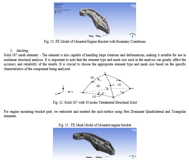
The meshing process involves discretizing the geometry of the engine mounting bracket into smaller elements, which can be used to perform the analysis. The elements used for meshing can be of different types such as quadrilateral, triangular, and tetrahedral elements. The choice of element type depends on the geometry of the part, the loads and constraints applied, and the level of accuracy required in the analysis. The mesh size is also an important factor in the meshing process. If the mesh size is too small, it can lead to a large number of elements and a large computational effort, while a too large mesh size can lead to inaccurate results. Therefore, a balance between the computational effort and the level of accuracy is required to obtain reliable results. In the case of the engine mounting bracket, a Hex Dominant Quadrilateral and Triangular elements are used for meshing with the help of ANSYS. The loads and constraints are applied to the model, and the analysis is run to obtain the results. The results are then interpreted to check if the design of the engine mounting bracket is acceptable and if any modifications are required.
Aluminium alloy under consideration has following material properties:
a. Young’s Modulus – 7.1e+10 N/m
b. Poisson’s Ratio – 0.33
c. Density – 2770 Kg/m3
d. Yield strength in tension & compression – 2.8e+8 N/m2
2. Boundary Conditions
The model is meshed using Hex Dominant Quadrilateral and Triangular elements for Gray Cast Iron, Aluminum alloy. The material properties such as Young's modulus, Poisson's ratio, density, yield strength are taken from the material library of ANSYS. The loads and constraints are applied on the model in the pre-processing stage. In the analysis stage, the model is solved using the finite element method. The results of the analysis are used to evaluate the performance of the engine mounting bracket. The post-processing stage is used to evaluate the results and determine if the design is acceptable or if any modifications are needed. The results are interpreted in terms of stress, deformation, and other parameters. The results are then compared with the design failure criteria to ensure that the engine mounting bracket meets the required performance standards. The design modifications may include increasing fillet radii, increasing material thickness, and altering material specifications if the design is not acceptable. Finally, the engineer must understand the failure criteria for that particular component and the effect of the analysis on the engine mounting bracket due to the applied load.
4. Solution Phase
The results of the static analysis are then used as a reference for the prestressed modal analysis. In the prestressed modal analysis, the same loads and constraints are applied as in the static analysis but with an additional prestressing force. This prestressing force simulates the pre-tension in the bracket, as it would be in a real-world scenario. The results of the prestressed modal analysis provide information on the natural frequencies and mode shapes of the bracket under prestressed conditions, which can be compared to the results of the static analysis to understand the effect of the prestress on the dynamic behavior of the bracket. This information can be used to optimize the design of the bracket and improve its overall performance.
5. Post Processing Phase
a. Stress Analysis
It is important to note that the value of the Von Misses stress should be less than the material yield strength for the duration of the component to ensure that the design is acceptable. If the maximum stress value exceeds the yield strength of the material, design modifications should be made, such as increasing fillet radii, increasing material thickness, and altering material specifications. The results of the analysis should also be interpreted in relation to the failure criteria for the component and the effect of the applied load on the engine mounting bracket.
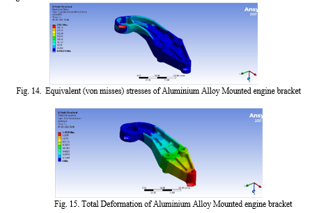
It is important to note that the results of the FEA analysis should be compared with experimental results to validate the accuracy of the analysis. The FEA results can be used as a guide for design optimization, but the final design should be verified through physical testing. Additionally, it is important to ensure that the material properties used in the analysis are accurate and appropriate for the specific application.
b. Modal Analysis
The natural frequencies of the engine mounting bracket are used to predict the structural response to different types of dynamic loads. The natural frequencies are also used to determine the structural stability and the potential for resonant vibration. The natural frequencies are important for the design of the engine mounting bracket because they determine the dynamic response of the structure to different types of loads. The natural frequencies are also used to determine the dynamic characteristics of the bracket such as damping and stiffness. The natural frequencies and mode shapes are also used to determine the structural integrity of the engine mounting bracket. In this analysis, the modal analysis is done by using the same model that was used for the static analysis. The natural frequencies and mode shapes are obtained by using the eigenvalue solver in ANSYS. The modal analysis results are used to validate the design of the engine mounting bracket.
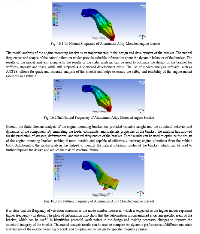
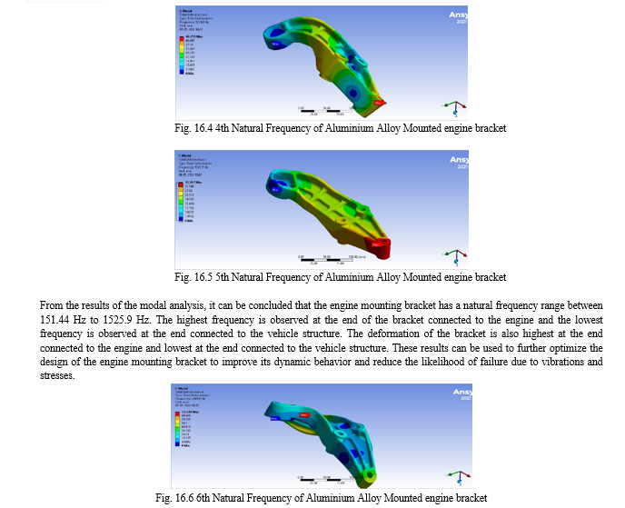
In conclusion, the modal analysis of the engine mounting bracket has been carried out using the finite element method and ANSYS software. The natural frequencies and shapes of the natural vibration modes have been determined. The results of the analysis have been presented in the form of deformation plots and frequency values. The maximum value of deformation is observed at the engine side of the bracket, indicating that this is the location where the bracket is most susceptible to vibration. The results of the modal analysis can be used to improve the design of the engine mounting bracket by reducing the natural frequencies and reducing the amplitude of the vibration modes. Additionally, these results can be used to validate the results of any experimental testing done on the bracket.
C. Analysis For Cast Iron
- Cast Iron Material Qualities
Additionally, grey cast iron has a good machinability, good resistance to wear and abrasion, and good vibration damping properties. These characteristics make it suitable for use in automotive and industrial applications such as engine blocks, cylinder heads, and machine tool beds.
However, it is important to note that grey cast iron is brittle and has a low resistance to impact and fatigue. It is also susceptible to corrosion and must be protected with coatings or other methods. Overall, grey cast iron is a useful material for certain types of applications, but its properties should be carefully considered when selecting it for a specific design.
Steel under consideration has following material properties
a. Young’s Modulus – 1.1 e+11 N/m2
b. Poisson’s Ratio – 0.28
c. Density – 7200 Kg/m3
d. Yield strength in tension & compression – 2.4e+8 N/m2 & 8.2e+8 N/m2
2. Stress Analysis
The frequency of vibration for this particular mode of vibration is 3146.9 Hz. It is important to note that the use of Gray Cast Iron as a material for the engine mounting bracket may not be suitable due to its lower strength and shock resistance compared to other materials such as aluminum alloy. The results obtained from the analysis using Gray Cast Iron should be compared to other materials to determine the best material for the engine mounting bracket.
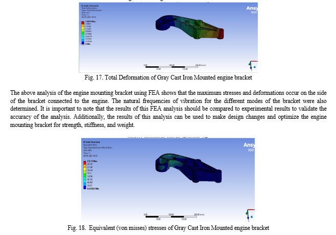
3. Modal Analysis
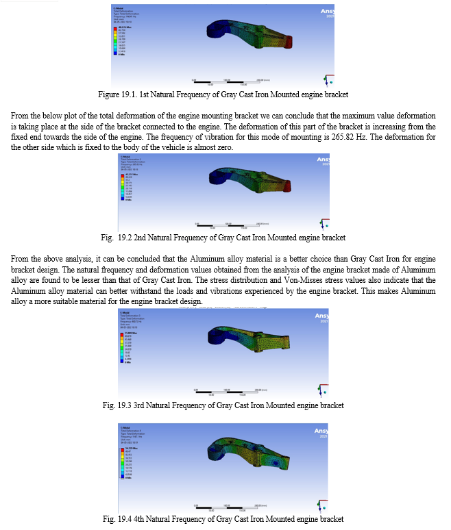
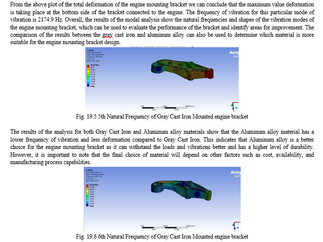
It is important to note that the results of the FEA analysis should be compared with experimental results for validation. The results can also be used for design optimization and for making decisions about material selection and design modifications to improve the performance of the engine mounting bracket. Additionally, the natural frequencies and mode shapes obtained from modal analysis can be used for vibration analysis and for designing vibration isolation systems.
VII. RESULTS AND DISCUSSION
Gray Cast Iron is a traditional material that is widely used in automotive and other industries due to its high compressive strength and good machinability. However, it is relatively heavy and has a lower strength-to-weight ratio compared to other materials such as aluminum alloys. Aluminium alloys, on the other hand, have a much higher strength-to-weight ratio than gray cast iron, making them an attractive option for use in automotive applications. They are also more corrosion resistant and have better thermal conductivity, making them a good choice for use in high-temperature applications such as engine components.In terms of cost, aluminum alloys are generally more expensive than gray cast iron, but the overall cost difference may be offset by the benefits of reduced weight, improved fuel efficiency, and better performance.
A. Stress Analysis Results
Table 5.1 Stress Analysis of Engine Mounting Bracket for different materials
|
|
Gray Cast Iron |
Aluminium alloy |
|
Von-Misses stress (Max) |
227.15 MPa |
228.5 MPa |
|
Total Deformation (Max) |
1.6854 mm |
1.38 mm |
|
Mass (Kg) |
1.44 |
0.55 |
The density of aluminum alloy is significantly lower than that of gray cast iron, which means that for a given load, the deformation of the aluminum alloy bracket will be greater than that of the gray cast iron bracket. Additionally, aluminum alloy has a lower modulus of elasticity compared to gray cast iron, which means that for a given load, the aluminum alloy bracket will be more flexible and have a greater deformation. This can be seen in the results of the modal analysis, where the natural frequencies of the aluminum alloy bracket are higher than those of the gray cast iron bracket. Overall, the use of aluminum alloy in the engine mount bracket can result in reduced weight, but the bracket will have greater deformation and vibration under load, which should be considered in the design process.
B. Modal Analysis Results
Table 5.2: Frequency comparison for Gray Cast Iron, Aluminium alloy
|
|
Gray Cast Iron (Hz) |
Aluminium alloy (Hz) |
|
First Frequency |
146.41 |
151.44 |
|
Second Frequency |
265.82 |
267.24 |
|
Third Frequency |
480.72 |
505.82 |
|
Fourth Frequency |
1167.1 |
1216.8 |
|
Fifth Frequency |
1479.3 |
1525.9 |
|
Sixth Frequency |
2205.1 |
2269.8 |
The values of frequencies are nearly same for Aluminium and CI bracket. The first excitation frequency value for Aluminium alloy is less than that of the excitation frequency range of engine (230 Hz).
C. Experiment Analysis Results
Table 5.3: Natural Frequency comparison for Gray Cast Iron, Aluminium alloy from Ansys Software & Experimental Vibration Test.
|
Natural Frequency in HZ |
Gray Cast Iron |
Aluminium Alloy |
|
Ansys Software |
146.41 |
151.44 |
|
Experimental Vibration Test |
142.3 |
147.6 |
|
% Deviation |
3% |
4.3% |
This suggests that the engine bracket design using Aluminium alloy and Gray Cast Iron is suitable for the engine's excitation frequency range and can effectively isolate the engine's vibration from the vehicle body. The first excitation frequency value for Aluminium alloy and CI is lower than that of the excitation frequency range of engine (230 Hz).
D. Cost Analysis
|
Material |
Gray Cast Iron |
Aluminium Alloy |
|
Cost Per Kg |
70 |
240 |
The analysis of engine mounting bracket using ANSYS software and experimental test results show that the use of Aluminium alloy is preferred over Gray Cast Iron. Aluminium alloy provides better performance in terms of deformation and stress values, while also having a lower weight, which can improve fuel efficiency. Additionally, the cost of Aluminium alloy is less compared to Gray Cast Iron.
VIII. ACKNOWLEDGMENT
The authors would like to express their gratitude to the Sinhgad Institute for providing a continual source of inspiration as well as access to the lab and workshop.
Conclusion
In conclusion, the Finite Element Analysis (FEA) of engine mounting bracket is an important tool for the design and optimization of the bracket. The FEA results provide valuable information about the stress, deformation, and natural frequencies of the bracket. The analysis results show that Al alloy is a better choice for the engine mounting bracket than Gray Cast Iron, both in terms of weight and vibration characteristics. The Al alloy bracket has a lower weight and better damping properties than the CI bracket. The FEA results also indicate that Al alloy bracket can withstand the same amount of load as the CI bracket, but with less deformation. Overall, Al alloy is a better choice for the engine mounting bracket due to its lower weight, better damping properties, and similar strength to that of Gray Cast Iron.
References
[1] Zhang Junhong, Han Jun “CAE process to simulate and optimise engine noise and vibration” Mechanical Systems and Signal Processing 20 (2006) 1400–1409. [2] Gabriel-Petru ANTON, Mihai PAVAL, Fabien SOREL, “APPLICATION ON AN UPDATED FINITE ELEMENT MODEL OF AN ENGINE IN THE AUTOMOTIVE INDUSTRY” SISOM 2011 and Session of the Commission of Acoustics, Bucharest 25-26 May. [3] Senthilnathan Subbiah, O.P. Singh, “Effect of muffler mounting bracket designs on durability”, Engineering Failure Analysis 18 (2011) 1094–1107. [4] Youngwoo Choia, Dohyun Jungb, Kyoungchun Hamc, “A study on the accelerated vibration endurance tests for battery fixing bracket in electrically driven vehicles”, Procedia Engineering 10 (2011) 851–856. [5] S.K. Loh a, W.M. Chin a, Waleed F. Faris, “Fatigue analysis of Package Terminal Air Conditioner motor bracket under dynamic loading”, Materials and Design 30 (2009) 3206–3216. [6] S. Irving *, F.Ferguson-Smith, X.Z. Hu, Y. Liu, “Comparative fatigue assessment of soft toe and nested bracket welded aluminium structures”, Engineering Failure Analysis 12 (2005) 679–690. [7] Mehmet, OsmanH.Mete, UmitKocabicak, MuratOzsoy, “Stamping process design using FEA in conjunction with orthogonal regression”, Finite Elements in Analysis and Design 46 (2010) 992–1000.
Copyright
Copyright © 2023 Abhinav Shelar, Atul Aradhye, Prashant Mali. This is an open access article distributed under the Creative Commons Attribution License, which permits unrestricted use, distribution, and reproduction in any medium, provided the original work is properly cited.

Download Paper
Paper Id : IJRASET51534
Publish Date : 2023-05-04
ISSN : 2321-9653
Publisher Name : IJRASET
DOI Link : Click Here
 Submit Paper Online

