

Ijraset Journal For Research in Applied Science and Engineering Technology
Analysing the Effect of Composite Ply Counts & their Orientation on the Vibration Frequency of a Wind Turbine Blade
Authors: Anirudh Vaidison, Sunny Kumar Barnwal, Anup Sharma
DOI Link: https://doi.org/10.22214/ijraset.2025.66835
Certificate: View Certificate
Abstract
Wind turbine blades are subjected to various loading conditions, including extreme weather. Modern wind turbine blades are typically made from composite materials, making it essential to map the structure of these composites to their mechanical properties. This study examines the vibration frequency response of a wind turbine blade as a function of ply count and fiber orientation in the composite material. The findings indicate that as the number of plies in the composite increases, the influence of fiber orientation decreases. However, a higher ply count also results in increased vibration frequencies, which may not be desirable for practical applications. This research aims to identify an optimized set of material parameters that can be mapped to achieve specific desired properties.
Introduction
I. INTRODUCTION
Wind turbine blades are a critical component in capturing renewable energy. These blades are large, slender, and flexible composite structures with a complex pre-bent and twisted geometry¹. They undergo large deflections and rotations due to external loads such as aerodynamic, inertial, and control actuator loads¹. These loads can lead to various structural issues in the blades. One of the significant structural issues is damage induced by fatigue loads³. Fatigue loads are repetitive loads that can cause the material of the blade to weaken over time, leading to cracks and eventually failure³.
Another issue is the leading-edge erosion caused by the exposure of blades to airborne particulates³. This can lead to damage ranging from minor outer surface erosion to total destruction of the blade4. The effects of wind load on the blade can also be exacerbated by the blade's flexibility?. A significant reduction of the rotor power is observed especially at large wind speed when considering the blade flexibility, which is proved mainly due to the blade torsion deformations instead of the pure-bending deflections6. Moreover, the blade structural model fidelity can significantly affect the wind turbine load analysis and computation time¹. Increasing the number of bodies in the formulation of the blade increases both the fidelity of the structural model and the size of the problem¹. The above issues can significantly affect the performance and lifespan of the wind turbines. Therefore, it is crucial to consider these factors in the design and maintenance of wind turbine blades².
On many previous studies, the Finite Element Method (FEM) has been used in the structural analysis of wind turbine blades7,8,9,10,11. This numerical technique allows for the prediction of the performance of wind turbines under various conditions9. One of the significant applications of FEM is in the static analysis of composite wind turbine blades8. This involves determining stress distribution, deflections, and fatigue behaviour under static and dynamic loading8. The results of such analyses are crucial for checking the strength of the blade and avoiding blade failure9.
FEM is also used in the study of the mechanical and thermal properties of wind turbine blades11. This helps in understanding the efficiency of the wind turbine based on the design of the blade and the material used11. Moreover, FEM has been used in the numerical modelling and simulation analysis of wind blades¹. This has become crucial for the design and optimization of wind blades7. The study of blade performance under various wind conditions has been made possible through the use of simulation analysis7.
Furthermore, FEM has been used in the aeroelastic formulation to predict the performance of an isolated horizontal axis wind turbine9. This involves deriving the equations of blade aeroelasticity based on a nonlinear beam model coupled with unsteady sectional aerodynamics9. The Finite Element Method provides valuable insights into the performance and structural integrity of the blades under various conditions, thereby aiding in their design and optimization10.
Composite materials are designed to optimize properties based on fiber and matrix properties, microstructure, and stacking sequences. The design process involves micromechanical and macro-mechanical analyses. Despite the complexity of failure phenomena, theories continue to be developed to improve design and analysis.
Traditional composites for wind turbine blades include glass fibers/epoxy matrix composites12. However, natural composites, hybrid, and nanoengineered composites are also being explored12. Carbon fiber composites have been recognized for their excellent performance in large-scale wind turbine blades13. Despite the challenges, the application of carbon fiber composites in wind turbine blades is being studied extensively, with a focus on improving cost, embedded energy, and carbon footprint13. The manufacturing technologies for these composite wind turbine blades are continually evolving12,13,14,15.
This study analyses the effect of material properties of composites on the structural performance of a wind turbine blade. A numerical model based on finite-element method is used to predict the vibration frequency response of a wind turbine blade. The modal frequency is simulated for 4 sets of composite ply counts and four sets of ply orientation. Such a comprehensive study can optimise the fabrication of wind turbine blades and lead to enhanced efficiency of renewable energy production.
II. METHODOLOGY
This work performs a finite element analysis (FEA) of a wind turbine blade for evaluating the effect of material properties like ply count and orientation on the vibration frequency of the blade structure. A commercial FEA software (Abaqus) is used to perform the parametric analysis with simulations.
A. Mathematical Model
Let’s consider a coordinate system where the z-axis aligns with the rotation plane and extends along the bending axis, while the y-axis deviates from the direction facing the wind by the coning angle Here, ‘u’ represents the unit displacement along the x-axis, and ‘v’ denotes the unit displacement along the y-axis.
The beam bending is governed by the following equations as explained by Perkins et al.16:
d2ydz2=11-dvdz232=-1E1 MXIYY+MYIXYIXX IYY-IXY2 (1)
d2udz2=11-dudz232=1E1 MYIXX+MXIXYIXX IYY-IXY2 (2)
The general equations for bending stress at point (x, y) in some cross-section plane is
σZZ=-EE1MXIYY+MYIXYY-MXIXY+MXIXYXIXX IYY-IXY2 (3)
The equation for the motion for the flexural vibrations of a beam allowing coupling between vibrations in orthogonal directions are (see appendix B)
v = -E1m ∂2∂z2IXX∂2∂z2 v + IXY ∂2∂z2 u 4
u=-E1m ∂2∂z2IYY∂2∂z2 u+IXY ∂2∂z2 v 5
Where
v=d2dt2 v
u=d2dt2 u
m=linear mass density
B. Finite Element Formulation
Figure 1 depicts the design of the blade on the left and the tetrahedral mesh of the structure on the right. The overall length of the blade is 50 meters and the diameter at the base is 5 meters.
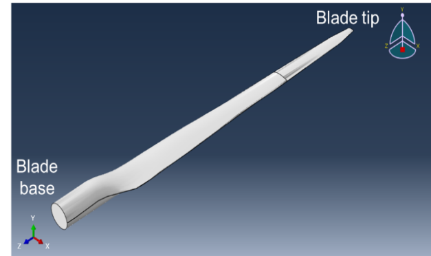
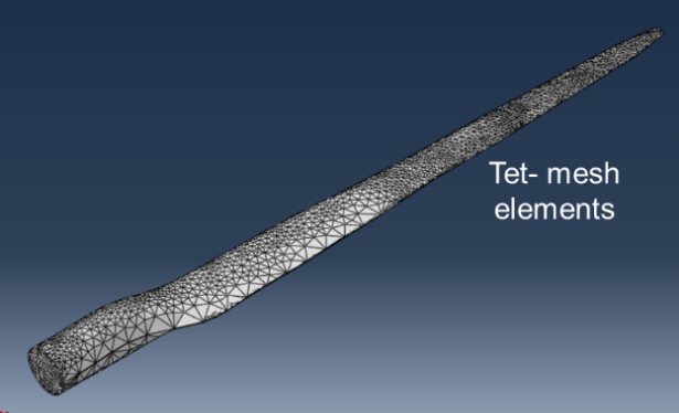
Figure 1. Blade Design used in the FEA simulations
The elastic material properties (orthographic engineering constants) used in the model are summarised in table 1.
Table 1. Material Properties of the blade
|
Modulus of elasticity |
Poisson’s ratio |
Shear modulus |
||||||
|
E1 |
E2 |
E3 |
ν12 |
ν13 |
ν23 |
G12 |
G13 |
G23 |
|
53480 |
17700 |
17700 |
0.278 |
0.278 |
0.24 |
5830 |
5830 |
12390 |
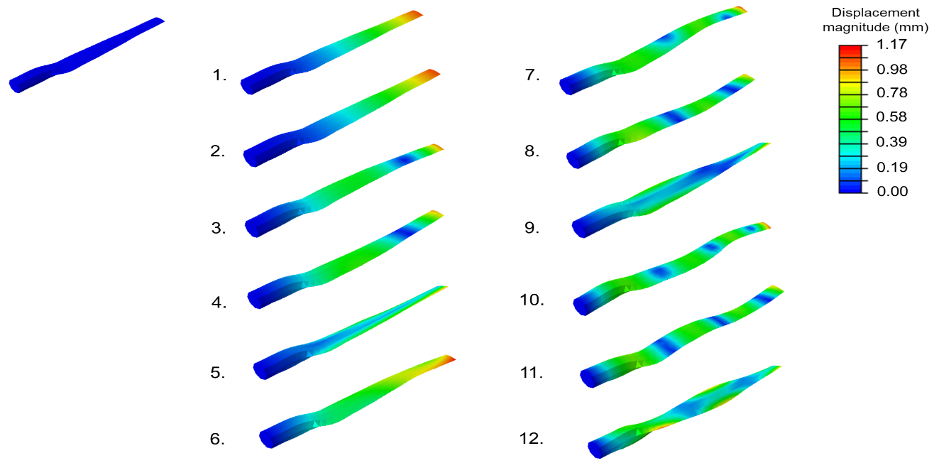
Figure 3. Blade displacement at 12 different frequency modes
Three different conditions are generally faced by wind turbine blades. The schematic description of the load applied on the wind turbine blade is presented in figure 2.
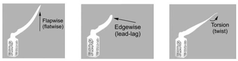
Figure 2. Loading conditions
This work performs modal analyses for 12 modes of frequencies in Abaqus/ Standard TM using the frequency module. Used linear S3 element which is 3-node triangular general-purpose shell element.
A parametric study was conducted by performing the simulation for modal frequency at the following:
A) 4 sets of composite ply counts: 3,6,12,24
B) 4 sets of ply orientation:
1. 0°and 90° alternatively
2. 45° and -45° alternatively
3. 0°, -45°,90°,45°
4. 0° and 45° alternatively
III. RESULTS AND DISCUSSION
Figure 3 displays the blade displacement contours at 12 different frequency modes with the blade having ply count of 24 and ply orientations of 0 and 45° alternately. The displacements are maximum at the tip of the blade with its base having the fixed boundary condition. The 12 deformation modes correspond to the 12 different eigen values. First 6 modes seem to show a wave-like deformation with higher wavelength and higher displacement at the tip whereas the next 6 modes correspond more towards the lower wavelength behaviour of the blade.
Frequencies at every mode were compared for the blade structure with different ply counts. The ply orientation combination was kept equal for all (0 and 90° alternate).
The frequencies at the modes for all the ply count cases was found to increase with the increase in the mode number (one mode corresponds to a particular eigen number, this number is higher for a higher frequency mode number) as seen in Figure 4. This observation is consistent with the contour results of the figure 3, where earlier modes were having higher wavelength behaviour relative to other modes (which also explains the relative flatness of the blade in first 6 modes and wavier like behaviour in next 6). The lower wavelength behaviour in the later modes from figure 3 can be verified as well as quantified from higher frequencies of the corresponding modes in figure 4.
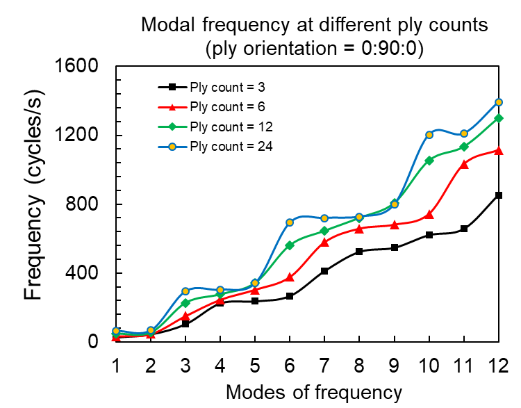
Figure 4. Modal frequencies at different ply counts (for ply orientation = 00:900:00)
The increase in the frequency per mode with increase in the ply count can be attributed to the increased thickness of the ply and subsequent material stiffness. Further the modal frequencies at different ply orientations (discussed in mathematical model section) for a constant ply count of 12 were simulated and the results are depicted in Figure 5. The results till mode 6 predicted less standard deviation in the frequencies of 4 orientations. However, the standard deviation started to increase with further to mode 12, where the difference between minimum and maximum frequency was ~25% of the minimum.
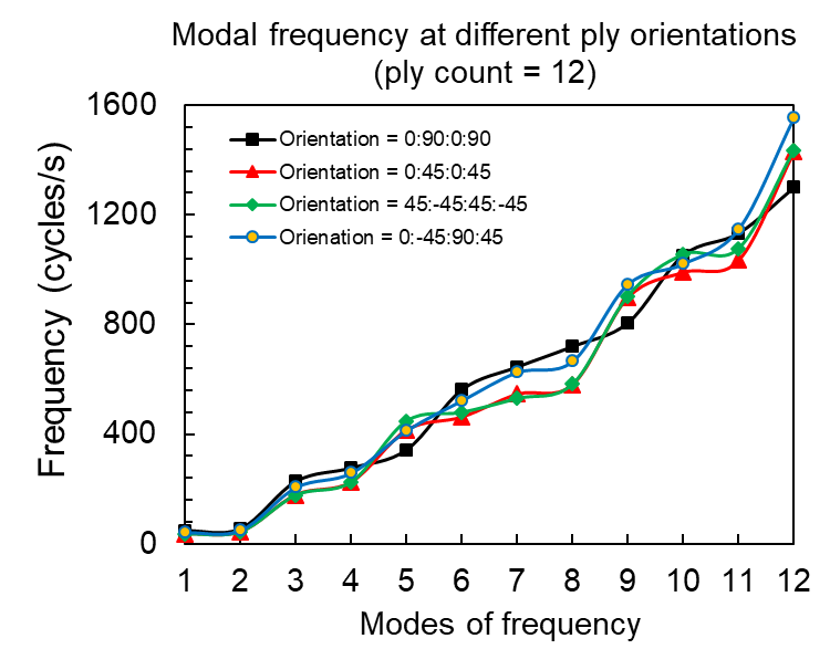
Figure 5. Modal frequencies at different ply orientations (for ply count = 12)
A similar simulation was performed as of Figure 5, with an increased ply count of 24. However, the difference in the frequencies was found the most at the 6th frequency mode, while the deviations at other modes (except 7 and 11) were very low, making the frequency nearly independent of ply orientations. It must be noted that the frequencies of vibrations are more in this case than the previous one owing to the increased strength of the ply set.
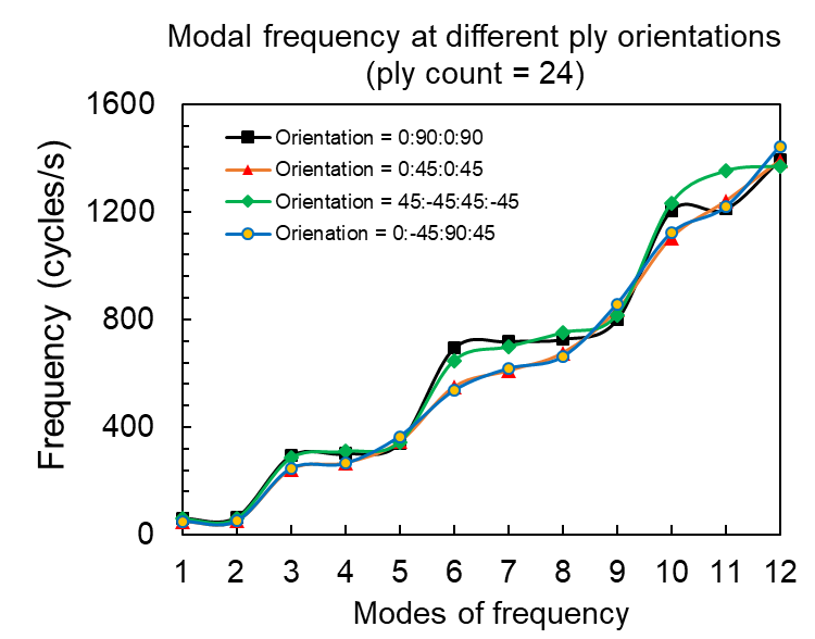
Figure 6. Modal frequencies at different ply orientations (for ply count = 24)
The standard deviations per mode from Figure 5 (ply count 12) and Figure 6 (ply count 24) was summarized and plotted in figure 7.
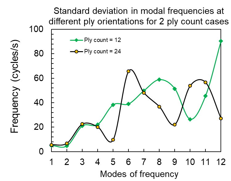
Figure 7. Standard deviation in modal frequencies at different ply orientations for two ply count cases (for ply counts = 12 and 24)
The standard deviation for the ply count of 24 kept lower for most of the nodes than that for the other case. This behavior of lower standard deviation across the ply orientations and across the modes can be attributed to the possible override by the increased strength with 24 plies. Further a statistical comparison of two-ply count cases across 4 ply orientation combinations in figure 5 and 6 is performed in table 2. While the modes with minimum and maximum frequency for two cases would always remain same for both, the ply orientations corresponding to such values (figure 5and 6) are different. Modes with maximum standard deviations are also different for two different cases.
|
Ply count |
Frequency mode and ply orientation with maximum frequency |
Frequency mode and ply orientation with minimum frequency |
Frequency mode and ply orientation with maximum standard deviation |
Frequency mode and ply orientation with minimum standard deviation |
||
|
Mode |
Orientation |
Mode |
Orientation |
Mode |
Mode |
|
|
12 |
12 |
0:-45:90:45 |
1 |
45:-45:45:-45 |
12 |
2 |
|
24 |
12 |
45:-45:45:-45 |
1 |
0:45:0:45 |
6 |
1 |
Conclusion
The simulations performed on 4 sets of ply orientations and 2 sets of ply counts shed light on their individual effect into the frequency modes. 1) Blade with ply count of 12 showed significant dependency on the ply orientations, while the one with ply count of 24 showed lesser dependency on ply orientations. 2) Lesser dependency on ply orientations was attributed to the possible override by the strength of 24 plies over other dimension dependent factors. 3) However, higher strength in ply count also contributed to higher frequencies of vibration and that can be non-recommended for the use. 4) A ply count with a suitable ply orientation combination with lower vibrational frequency as well as sufficient ply set strength can be optimized through this method of study for a larger data set.
References
[1] Gözcü, Ozan, and David R. Verelst. \"The effects of blade structural model fidelity on wind turbine load analysis and computation time.\" Wind Energy Science 5.2 (2020): 503-517. [2] Li, Xiang, et al. \"Thermal inspection of subsurface defects in wind turbine blade segments under the natural solar condition.\" IEEE Transactions on Industrial Electronics (2023). [3] Zhu, Xiaocheng, et al. \"Impact of blade flexibility on wind turbine loads and pitch settings.\" Journal of Solar Energy Engineering 141.4 (2019): 041002 [4] Alrowwad, Ibrahim, Xiaojia Wang, and Ningling Zhou. \"Numerical modelling and simulation analysis of wind blades: a critical review.\" Clean Energy 8.1 (2024): 261-279. [5] Katsaprakakis, Dimitris Al, Nikos Papadakis, and Ioannis Ntintakis. \"A comprehensive analysis of wind turbine blade damage.\" Energies 14.18 (2021): 5974. [6] Gözcü, Ozan, and David R. Verelst. \"The effects of blade structural model fidelity on wind turbine load analysis and computation time.\" Wind Energy Science 5.2 (2020): 503-517. [7] Ozyildiz, Meltem, and Demirkan Coker. \"Static analysis of a composite wind turbine blade using finite element model.\" MARINE VII: proceedings of the VII International Conference on Computational Methods in Marine Engineering. CIMNE, 2017. [8] Calabretta, A., et al. \"Finite element analysis of horizontal axis wind turbines performance.\" MARINE VI: proceedings of the VI International Conference on Computational Methods in Marine Engineering. CIMNE, 2015. [9] Boudounit, Hicham, et al. \"Structural analysis of offshore wind turbine blades using finite element method.\" Wind Engineering 44.2 (2020): 168-180. [10] Bak Mohamed, K., et al. \"Structural and Thermal Analysis of Composite Wind Turbine Blade for Wind Mill Applications.\" Advances in Design and Thermal Systems: Select Proceedings of ETDMMT 2020. Springer Singapore, 2021. [11] Mishnaevsky Jr, Leon, et al. \"Materials for wind turbine blades: An overview.\" Materials 10.11 (2017): 1285. [12] Teng, Hanwei, et al. \"Carbon fiber composites for large-scale wind turbine blades: applicability study and comprehensive evaluation in China.\" Journal of Marine Science and Engineering 11.3 (2023): 624. [13] Mishnaevsky Jr, Leon. \"Composite materials for wind energy applications: micromechanical modeling and future directions.\" Computational Mechanics 50.2 (2012): 195-207. [14] Mishnaevsky Jr, Leon, et al. \"Materials for wind turbine blades: An overview.\" Materials 10.11 (2017): 1285. [15] Teng, Hanwei, et al. \"Carbon fiber composites for large-scale wind turbine blades: applicability study and comprehensive evaluation in China.\" Journal of Marine Science and Engineering 11.3 (2023): 624. [16] Perkins, Fredrick W., and Duane E. Cromack. \"Wind turbine blade stress analysis and natural frequencies.\" (1978).
Copyright
Copyright © 2025 Anirudh Vaidison, Sunny Kumar Barnwal, Anup Sharma. This is an open access article distributed under the Creative Commons Attribution License, which permits unrestricted use, distribution, and reproduction in any medium, provided the original work is properly cited.

Download Paper
Paper Id : IJRASET66835
Publish Date : 2025-02-04
ISSN : 2321-9653
Publisher Name : IJRASET
DOI Link : Click Here
 Submit Paper Online