Ijraset Journal For Research in Applied Science and Engineering Technology
- Home / Ijraset
- On This Page
- Abstract
- Introduction
- Conclusion
- References
- Copyright
Wearable Antennas for Health Monitoring Systems
Authors: Sparshitha Liyona, Nithyashree PJ, Shreyas Shetty, Supriya G, Aswini GV, Shwethaa AR
DOI Link: https://doi.org/10.22214/ijraset.2025.66454
Certificate: View Certificate
Abstract
This paper consolidates and synthesizes two detailed IEEE studies on wearable antennas designed for health monitoring systems. The antennas operate at key frequencies in the ISM band (2.3 GHz, 2.4 GHz, and 2.66 GHz), addressing the need for compact, efficient, and safe designs suitable for telemedicine applications. This research explores design methodologies, material considerations, and performance metrics, including return loss, VSWR, gain, and Specific Absorption Rate (SAR). The findings demonstrate the feasibility and practicality of wearable antennas in real-time health monitoring, paving the way for innovations in remote healthcare systems. While conventional copper metal sheets have been used as antenna conductive material. The antenna proposed is designed and simulated using CST simulator, fabricated using flexible copper sheet and tested. On the receiving section the data is collected through the receiving antenna connected to RF module and processed for further analysis of health parameters. A wearable antenna is designed for transmitting and receiving signals at 2.4GHz. A rectangular patch antenna is designed with slots to enhance directivity and good impedance matching with the other RF circuits. The antenna is simulated using Ansys HFSS v19, fabricated and tested which gives a VSWR of 1.5 and Return loss of -14dB.The gain of the antenna is 5.2dB. Further the collected data is visualized and can be analyzed by the supervisor by logging onto the webpage and accessing the health parameters.
Introduction
I. INTRODUCTION
The growing demand for remote and non-invasive health monitoring solutions has led to the development of wearable antennas. These antennas are critical components in wireless health monitoring systems, enabling real-time transmission of health parameters such as heart rate and body temperature. Operating in the ISM band, wearable antennas must be compact, efficient, and safe for prolonged use. This paper compares two studies focusing on the design and performance of wearable microstrip patch antennas, emphasizing their applications in telemedicine. In fact, non-invasive wearable sensors can be combined with information technologies methods helping the elderly people to receive the needed assistance, in spite of just living in their homes, compared to living in impersonal and costly This paper includes patch antenna design which is made from copper metal sheets as a conducting material with two types of substrate materials that will be discussed in detail in the subsequent sections. Further, this paper studies the SAR (specific absorption rate) calculations for the proposed antenna in, an on the body environment which ensures proper operations in the vicinity of the human body. The RF system considered in this paper consists of designing a microstrip patch antenna at 2.4GHz. The designed antenna is then integrated with RF transceiver. The purpose of using RF transceiver is that frequency is very high and noises are reduced. As the size of the device is small, the whole system gets compact. RF module can associate through SPI (Serial Peripheral Interface) and many more features like low power modes, multiple channels, channel hopping, frequency calibration and retransmit. The nRF2L01RF transceiver used in the research work is from Nordic Semiconductor Link operating at 2.4GHz frequency. This module can be easily integrated to other RF devices and due to its low-cost hardware, it is reliable in telemetry and consumer applications. The method of communication is established with the help of Arduino, RF transceiver module and RF transmitting and receiving antenna. Health parameters like temperature and heart rate are sensed using LM35 and pulse sensor-SEN-11574 respectively. The sensor picks up the health parameters and the controller analyses the data which is transmitted through RF module. The sensors along with the transmitter side are clipped onto the human body from whom the health parameters are needed and through the sensors, the readings are collected. The observed data is processed and transmitted with the help of the transceiver module through the designed transmitting microstrip patch antenna. On the receiving section the data is collected via the receiving antenna and the transceiver module and processed by the controller. A webpage is created and collected data are saved in it. Further these collected data can be visualized by the doctor by logging onto the webpage and accessing the patient details, analyze the parameters, thus helping to monitor the health of the patient
II. DESIGN AND METHODOLOGY
Both studies employed microstrip patch antennas with variations in substrate materials and operating frequencies. The first study utilized an FR4 substrate with a dielectric constant of 4.4 and a thickness of 1.6 mm, optimizing the design for 2.4 GHz. The second study explored the use of flexible substrates, including denim fabric and FR4 (lossy), operating at 2.3 GHz and 2.66 GHz. Simulations were conducted using HFSS and CST Microwave Studio to evaluate performance metrics.
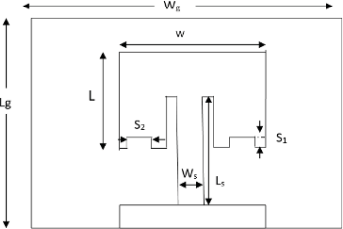
Figure 1: Geometrical design of the microstrip patch antenna.
The microstrip antenna performance depends on its dimension. Dimensions of the patch are fixed depending on the operating frequency, dielectric of the substrate and height of the substrate. The patch width (W) and length (L) are calculated using the following theoretical principle
1) ????????????????? ???????? ????????? ????????????????? is calculated using?
-
-
- C : ???????????????????? ???????? ????????????????? (3 ∗ 108, ????/????)
- ????????: ????????????????????????????????????????????????????????????????????(????????????????)
- ∈???? : ???????????????????????????????????????? ???????????????????????????????? ???????? ????????? ????????????????????????????????????
-
2) ???????????????????????????????????????????????????????????????????????????????????????????????????????????? (∈????????????):
????????? ???????????????????????????????????? ???????????????????????????????????????? ???????????????????????????????? ???????????????????????????????? ???????????? ????????? ???????????????????????????????? ???????????????????????? ???????????? ???????? ???????????????????? ????????:
-
-
- h: Height (thickness????) ???????? ????????? ????????????????????????????????????
- W: ????????????????? ???????? ????????? ?????????????????
-
3) ???????????????????????????????????? ????????????????????? (????????????????):
????????? ???????????????????????????????????? ????????????????????? ???????? ????????? ????????????????? ????????:
4) ????????????????????? ???????????????????????????????????? (?????):
????????? ???????????????????????????????????????? ????????????????????? ???????????? ???????? ????????? ???????????????????????????????? ???????????????????????? ????????:
5) ???????????????????????? ????????????????????? ???????? ????????? ????????????????? ():
????????? ???????????????????????? ????????????????????? ???????? ????????? ????????????????? ???????? ???????????????????????????????????????? ????????:
???? = ???????????????? − 2?????
The parameters used to design the proposed microstrip patch antenna are shown in the Table:
|
Parameters |
Value in mm |
|
L |
28.316 |
|
W |
38.04 |
|
???????? |
52.316 |
|
???????? |
62.04 |
|
???????? |
7.614.89754 |
|
???????? |
14.8975 |
|
????1 |
1.5 |
|
????2 |
4.5 |
Table: Dimensions of RF Transmitting Antenna
The simulation of the antenna is done in Electromagnetic simulation software Ansys HFSS v18. Fig. 4shows the surface current distribution of the proposed antenna at resonating frequency of 2.4 GHz. The S11parameters of the simulated result is shownin Fig. 5. The result shows an efficient approximation of -18dB. Fig. 6 shows the VSWR plot of the designed antenna. The VSWR of the antenna is seen to be 1.27 at 2.4GHz. The directivity is 5.2 dB along the elevation plane.The gain of the proposed antenna is also simulated using HFSS and is found to be around 3.7dB for the far field pattern.
III. RESULTS and Discussion
The designed antennas were evaluated based on return loss, VSWR, radiation patterns, and SAR. The rectangular patch antenna in the first study achieved a gain of 5.2 dB and a return loss of -14 dB at 2.4 GHz, while the denim-based antenna in the second study outperformed its FR4 counterpart with a return loss of -33.8 dB at 2.66 GHz
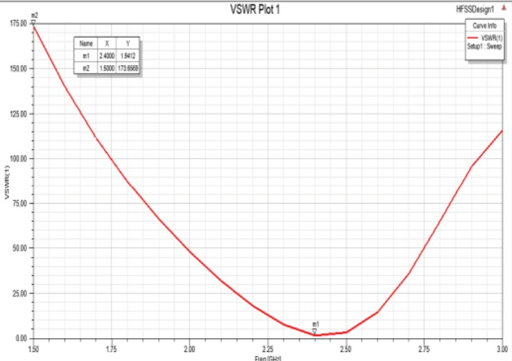
Figure 2: Return loss plot of the designed antenna
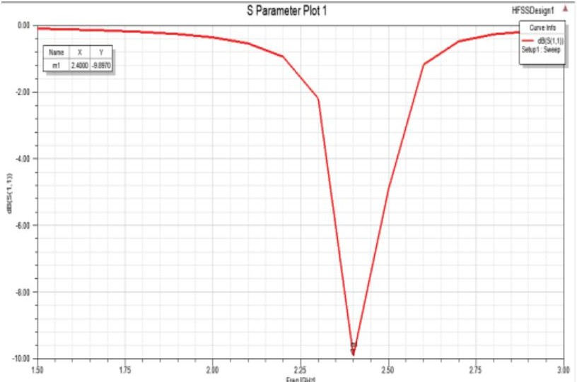
Figure 3: VSWR plot of the designed antenna.
The fabricated antenna on the FR-4 substrate its compact size of the antenna makes it very feasible for medical applications. Its overall dimension is 62x 47 x 1.6mm3 . The simulation and tested results of antenna is shown in table II. The performance is well matched with the simulation results; thus validating the use of antenna in practical purpose.
In general, an antenna having patch like structure is preferred in wearable applications. This configuration, in fact, would allow the antenna to produce platform tolerant performance and the overcome the electromagnetic compatibility issues as well; this in turn permits the operation of the antenna in the close vicinity of human body. In order to satisfy these requirements, the microstrip technology was chosen. The intended logo was created by properly shaping the edges of the patch antenna and by using the slots to reproduce the writing. A coplanar feed line which is slotted on the ground plane and shorted to the radiating element through a hole was used to match the impedance of the antenna to 50Ω, The dimensions of the patch antenna were refined and optimized to get the intended behaviour. For this purpose full- wave simulations were carried out using thes
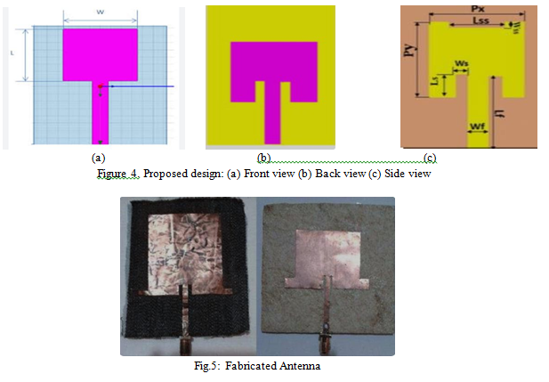
Commercially available software CST-MWS (Computer Simulation Technology Microwave Studio). Figure 1 shows sketch of the optimized antenna geometry. The width of the coplanar feed line is equal to 1.35 mm, the gap between the feed line and the ground is equal to 0.7mm. The diameter of the via hole is 0.5 mm. Figure 4 shows the top view, back view and side views of the patch antenna model with denim material having relative dielectric constant of €r = 1.67, a thickness of 0.5 mm for the substrate material. Here, the top layer is the patch antenna, the middle layer is the substrate, and the bottom layer is the ground. A similar antenna was designed with the antenna having a copper layer with thickness equal to 0.15 mm as conductive layer and the substrate being a layer of FR4(lossy) having relative dielectric constant of 4.3 and the thickness equal to 1.57 mm.
Figure 5 shows the front view and the back view of the fabricated antenna. A Vector Network Ananlyzer may be used to characterize the fabricated antenna. For the
measurements, a 50 Ω SMA connector is soldered to the antenna, to make connection to the VNA.
IV. FAR FIELD RADIATION [GAIN]
Radiation efficiency is an important parameter used to evaluate an antenna. Achieving good radiation efficiency is the ultimate goad in antenna testing. It gives accurate values for the device under test. Figure 5 shows the 3D representation of Far-field radiation pattern at 2.66 GHz operating frequency.
Applications: The far-field performance of these antennas ensures reliable communication for wearable health monitoring systems, even in non-line-of-sight conditions. This is particularly beneficial in remote monitoring scenarios, where the antenna must transmit data effectively through various obstacles.
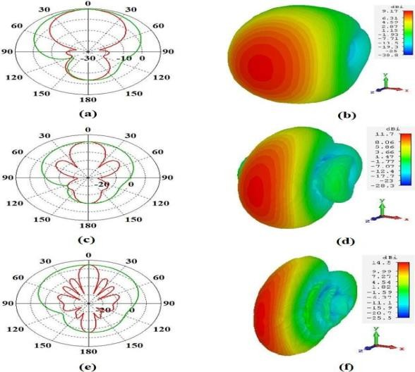
Fig 6 far field radiation pattern
Far-field radiation pattern of the antenna array, (a) polar pattern of 1×2 array, (b) 3D directivity pattern of 1×2array, (c) polar pattern of 1×4 array and (d) 3D directivity pattern of 1×4 array, (e) polar pattern of 1×8 array, (f) 3D directivity pattern of 1×8 array
Conclusion
This comparative study highlights the advancements in wearable antenna technology for health monitoring systems. The results validate the practicality of integrating these antennas into wearable devices, ensuring efficient communication and user safety. Future work should focus on exploring advanced materials, miniaturization, and incorporating machine learning algorithms for predictive health analytics. Certainly! Here is an expanded version of the conclusion incorporating written aspects of return loss, VSWR, gain, and GHz: The proposed antenna design achieved a significant return loss at the resonant frequency, indicating excellent impedance matching. The VSWR was measured to be within acceptable limits, ensuring minimal power reflection and efficient signal transmission. Moreover, the antenna demonstrated a gain of approximately 3.7 dB at the operating frequency of 2.66 GHz, confirming its suitability for wearable applications requiring reliable performance. Future work involves exploring advanced materials, miniaturization techniques, and incorporating multi-band functionality to further enhance the antenna\'s performance. Emphasis will also be placed on improving SAR compliance to ensure the safety of users while maintaining high efficiency and stable operation across varying environments.
References
[1] Swetha Amit et al., \'Design and Development of Wearable Antenna Integrated with RF Transceiver for Health Monitoring System,\' 2020 5th International Conference on Recent Trends in Electronics, Information, Communication & Technology (RTEICT), 2020. [2] Rekha P et al., \'Wearable Antenna for Remote Health Monitoring,\' 2023 International Conference on Intelligent and Innovative Technologies in Computing, Electrical and Electronics (IITCEE), 2023. [3] A. Sarma et al., \'Low return loss slotted rectangular microstrip patch antenna at 2.4 GHz,\' 2015 2nd International Conference on Signal Processing and Integrated Networks (SPIN), 2015. [4] G. Monti et al., \'Wearable logo-antenna for GPS–GSM-based tracking systems,\' IET Microwaves, Antennas & Propagation, 2016. [5] B. Gilbert, \'A Precise Four-Quadrant Multiplier with Subnanosecond Response,\' IEEE Journal of Solid State Circuits, 2020. [6] E. Heaney et al., \'Ultra-low-power Low Noise Amplifiers for Wireless Communications,\' GaAs IC Symposium, 1993. [7] R. Nakamura et al., \'Target Localization Using Multi-static UWB Sensor for Indoor Monitoring System,\' WiSNet, 2017. [8] P. Soh et al., \'Design of a Broadband All-Textile Slotted PIFA,\' IEEE Transactions on Antennas and Propagation, 2012. [9] D. L. Paul et al., \'A Low-profile Textile Antenna for Digital TV Reception,\' IEEE Radio and Wireless Symposium, 2012. [10] N. Chahat et al., \'60-GHz Textile Antenna Array for Body-centric Communications,\' IEEE Transactions on Antennas and Propagation, 2013.
Copyright
Copyright © 2025 Sparshitha Liyona, Nithyashree PJ, Shreyas Shetty, Supriya G, Aswini GV, Shwethaa AR. This is an open access article distributed under the Creative Commons Attribution License, which permits unrestricted use, distribution, and reproduction in any medium, provided the original work is properly cited.

Download Paper
Paper Id : IJRASET66454
Publish Date : 2025-01-10
ISSN : 2321-9653
Publisher Name : IJRASET
DOI Link : Click Here
 Submit Paper Online

