Ijraset Journal For Research in Applied Science and Engineering Technology
- Home / Ijraset
- On This Page
- Abstract
- Introduction
- Conclusion
- References
- Copyright
Analysis of Wind Response of Braced and Unbraced Tall Building
Authors: Mamta ., Vijay Kumar, Pradeep Kumar Nirmal, Anita Chaturvedi
DOI Link: https://doi.org/10.22214/ijraset.2024.64765
Certificate: View Certificate
Abstract
As high-rise buildings become increasingly prevalent worldwide, their complex structural components and the need for high stability pose challenges for safety and design requirements. The present study investigates the influence of bracing systems and plan aspect ratios on the ability of tall buildings to withstand wind loads. The study aims to analyze the effects of these variables on the wind-induced responses of tall buildings and improve bracing system design for structures with high aspect ratios. Numerical simulations using finite element analysis software are conducted, creating various building models with different aspect ratios and bracing systems. The displacement, drift, base shear responses and time period of each model are examined to evaluate the effectiveness of different bracing systems. The results highlight the significant impact of aspect ratio on the response to wind loads, with larger aspect ratios experiencing greater motion and stress. However, well-designed bracing systems prove effective in reducing wind-induced motion and stress. The study provides insights on best bracing system for different aspect ratios, offering valuable insights for creating safer and more resilient high-rise buildings.
Introduction
I. INTRODUCTION
High-rise construction projects (towers) are a reflection of the nation's economic might and a symbol of its characteristics. Many nations push for the creation of thorough plans to build high-rise investment projects in order to boost their stature and economic might in an effort to advance. The funding of such programs is a key factor in their success in nations like Malaysia, Hong Kong, the USA, the UK, Japan, etc.
After conducting thorough feasibility studies, a range of significant expenditures are made to ensure that the projects achieve the desired advantages for investors at the state and economic levels. These studies were carried out after thorough examination of the planning, marketing, and financial factors. Planning, economic development, and urban growth all contribute to a country's success; this is the main factor that promotes technical development by encouraging the use of cutting-edge tools and materials. All of those elements help to draw money into the nation. With the establishment of many principles and criteria to ensure the success of these plans, many nations began to advance toward the end of the 20th century by creating comprehensive plans to build high-rise investment projects. The majority of the Arab Gulf states, Hong Kong, and Malaysia have started these processes in an effort to improve their nations on a number of fronts, and feasibility studies have been crucial in identifying all the parts and factors that have an impact on the project and the level of success of the investing firms. With its four-story wooden residential structures, ancient Rome pioneered high-rise construction. Then, brick units were used to construct such residential structures. The sixteen- story Monadnock Building in Chicago was constructed in the 19th century in North America using the loadbearing wall construction technique. Buildings continued to rise in height as construction techniques improved, reaching 60 storeys in 1913 with the erection of the Woolworth Building in New York. For builders, high-rise structures are still appealing today. Due to their enormous presence in the built environment, high-rise structures hold a special significance and distinguishing characteristic because of their height, clarity, and dominance over other landscape features.
A. Wind Load Effects On Tall Buildings
This section describes how buildings behave when exposed to horizontal wind-load. The struggle to build taller buildings is always growing along with knowledge, technology, and building materials. It is not without difficulties and problems, though. First off, when a building gets taller, the vertical loads rise as well. Additionally, the building is significantly affected by the horizontal wind-load.
The behavior of the building under lateral loading can be compared to a cantilever that is fixed to the ground. Under the assumption that the wind has a uniform distribution, the base-moment grows quadratically with height. However, the actual shape of the wind pressure changes with height, increasing base-moment. The capacity of high-rise structures to absorb horizontal forces and transmit the resulting moment into the foundation is one of the key design considerations. Coupled load-bearing vertical walls are one efficient way to do this. However, the concrete walls on the laden side will experience tensile strains as a result. The self-weight of slabs, for example, is placed on the walls to create compressive pressures in an effort to reduce these stresses,The importance of taking into account the requirements for functioning as well as the selection of cross-sections, materials, and structural systems, increases with a building's height. Deflections and accelerations from horizontal loads, which primarily result from unanticipated deflections, wind, or earthquakes, are factors that need to be taken into account. Unexpected deflections may happen when materials have manufacturing defects or the foundation is uneven due to an uneven location. Any unexpected deflection creates additional lateral pressures that must be considered. The horizontal loading of the wind may cause the building to sway. This is so because oscillation is common in high-rise buildings.
B. Braced Frame And Types Of Bracing Systems
The extremely durable braced frame structural system is widely used in structures that are susceptible to lateral stresses, such as wind and seismic force. The components of a braced frame are frequently made of structural steel, which performs well in both tension and compression. The frame's beams and columns carry the vertical loads, and the bracing system supports the lateral stresses. However, because they might restrict the location of openings and facade design, bracing installation can be difficult. Due to this, bracing is now represented in high-tech or post-modernist architecturally influenced projects as an interior or exterior architectural component. One of the most vital and important components of buildings that contributes to their stability and ability to withstand earthquakes is bracing system. The braced frame is essentially a system that is constructed to withstand strong winds and seismic effects. The braced frame's members are not permitted to sway laterally. Bracings are offered to provide further protection against external loads. The steel elements that reinforce the braced buildings boost the tensile and compressive strength of the structure.
1) Advantages Of Bracing Systems
The employment of bracing systems in various constructions has a number of advantages.
- The primary beam of the structure is protected against buckling by the bracing systems.
- Equally distributing the vertical and lateral loads among the main beams.
- The requisite strength and stiffness can be obtained in a flexible, cost-effective manner.
- In comparison to non-braced buildings, the braced frames offer good resistance to high- speed winds and seismic forces.
- Using a bracing system has a number of benefits, one of which is a decrease in lateral movement.
2) Types Of Bracings
In the construction of structures, bracing methods often fall into one of the following two categories.
- Horizontal Bracing System-The horizontal bracing system is composed of bracings that are installed in horizontal planes at each level and that provide load paths so that horizontal forces may be efficiently transmitted to vertical bracing planes. To transfer horizontal loads from columns at the edge of the structure to the planes of vertical bracing, systems for horizontal bracing are developed. The wind pressure exerted on the building results in the development of horizontal stresses on the perimeter columns. The two main horizontal bracing methods used. in multistory braced steel buildings are diaphragms and discrete triangulated bracing. There are many floor systems for diaphragms; some, like composite floors, provide a perfect horizontal diaphragm, while others, like precast concrete slabs, call for special adaptations to be suitable for their intended application.
- Vertical Bracing System-The bracings in the vertical planes are positioned between the lines of the columns, providing the load channels that are utilized to transmit the horizontal forces to the ground level. This system will transmit the horizontal loads to the foundations and withstand the building's overall sway..
- Forward Bracing System-The diagonal bracings, which include the forward bracing systems, connect the bracing system to the end points diagonally. As seen in the figure 1, the forward bracing system model has four end points (identified by the numbers 1, 2, 3, and 4). The steel bracing system is attached between the first and fourth end points. The diagonal front bracing system frequently helps to reduce the X direction or Y direction storey drift values under lateral loading actions (wind load and seismic load values).
- Backward Bracing System-A backwards bracing system is the second kind of diagonal bracing. Although the value of storey drift falls in the opposite direction of forward bracings, the fundamental concept is the same. The full backward bracing type, which has four end points like the bay frame, is shown in the figure 2. The bracing system is connected to the second and third end points. This type of bracing system helps to decrease the amount that the building structure's storeys wander under lateral stress in either the X or Y orientations.
- V Type Bracing System-The third type, which is the vertical bracing system, includes the V type bracing system. In this scenario, limiting the vertical deflection is the key goal. Three points connect the bracing: one at one end's corner, one at the other end's corner, and one in the center of the opposing side. The assignment of the V-bracing model, which includes the five points 1. 2, 3, 4 and 5, is depicted in the figure 3. The points 1, 5, and lastly 2 are used to connect the bracings. providing V bracing system for building the vertical deflection value decreases to earth quake resistant buildings.
- Inverted-V Type Bracing System-Inverted-V type bracing systems are installed and aligned similarly to traditional V type bracings. This type likewise uses a five-point connection to connect the bare frame. The layout of the entire inverted-V type bracing system, which consists of the same five points-1, 2, 3,4 and 5-is represented in the figure 4. By aligning points 3, 5, and 4, the steel bracing system was properly connected. For this inverted V type bracing system scenario, the main benefit is a reduction in the vertical deflection value for the building structures.
- X Type Bracing System-The most popular sort of bracing system for managing deflection and drift is the X type. In this style, the bracings are attached in an X pattern to each corner point of the bare frame. The model of the entire bracing system, which consists of the four corners 1, 2, 3, and 4, is illustrated in figure 5. The points of 1 and 4, 2 and 3, which connect the bracings in two diagonal directions. The building will be in a stable condition with the help of the four joint connections at each corner. Under the application of lateral loading conditions. like seismic loading condition and wind load condition, the structure will not move in the X direction system or the Y direction system, and it will not move in the deflection direction (height direction) either.
- K Type Bracing System-The final type includes K type bracing systems. The ends of the bracing are attached to the center point of the bare frame in this particular bracing arrangement. The figure 6 depicts the entire K type bracing model, which consists of points 1, 2, 3, 4,5, 6, 7 and 8. The bracing model is connected to the naked frame's 5, 8, and 6 in the right-hand part and the bare frame's 5, 7, and 6 in the left. The increased stability in the building model as per the earthquake resistant building designs increases as a result of the center point of the bare frame connection for the bracing systems being present. Similar to how the value of the vertical deflection in a building structure diminishes under lateral loading conditions. such as earthquake and wind load conditions, according to IS 1893 code standards for earthquakes and IS 875 code standards for wind load standards.
C. Steel Concrete Composite Construction
The most significant and commonly used building materials are steel and concrete. With the steel being effective in tension and the concrete being successful in compression, they have approximately the same thermal expansion, making them a great combination of strengths. Additionally, concrete shields steel from corrosion, insulates it from heat at high temperatures, and helps prevent local or lateral torsional buckling in thin steel sections.Different structural components or elements of buildings may be created wholly of steel, entirely of reinforced concrete, or a combination of the two, depending on the circumstances. However, it is a reality that engineers are increasingly developing composite and mixed construction methods that combine structural steel and reinforced concrete to produce structures that are more efficient than those constructed from either material alone.
II. EXPERIMENTAL INVESTIGATION
A. Modelling Of Unbraced Tall Buildings
This chapter contains the analysis and design of RCC, Steel and Steel Concrete Composite building models with varying height and aspect ratio. To start with, buildings were modelled for a particular case by assigning various sections for slabs, decks, beams and columns. Then loads are applied as per the codes and analysis is done. The results of the analysis are used to design the building as per relevant codes.
B. General Data Used For Modelling
For the G+20 storey and G+30 storey buildings, the modelling, analysis and designing is done on ETABS software. The building is considered to be situated in Bhuj region of Gujrat where basic wind speed is 50m/s also it comes under the highest level of seismicity i.e.. seismic zone V. Therefore, the buildings are modelled for this case.
1) Loads, Material And Sections Provided
Table 1 Design Loads and Materials
|
Dead Load on Slab due to floor finish |
2KN/m2 |
|
Dead Load on outer beams due to Cladding |
1KN/m |
|
Live Load on Slab |
4KN/m2 |
|
Grade of Structural Steel |
Fe-250 |
|
Grade of Longitudinal Reinforcement |
Fe-500 |
|
Grade of Transverse Reinforcement |
Fe-415 |
|
Type of Support |
Fixed |
|
Storey Height |
3m |
|
Thickness of Slab |
125mm |
|
Thickness of Deck Slab |
100mm |
|
Thickness of Profiled Deck |
162,5mm |
|
Section used for Bracing |
ISA 150x150x10 |
|
|
|
2) Earthquake Load Data
For the design of buildings equivalent seismic load analysis is done using provisions given in IS 1893(Part 1): 2016. The buildings are considered to be situated in seismic zone V and are considered as general building. Two load cases are generated i.e., EQ X (earthquake load in direction of length of building) and EQ Y (earthquake load in direction of width of building).
3) Wind Load Analysis
The buildings are designed for wind load as per the provisions in IS 875(Part 3): 2015. The building is assumed to be situated in coastal area having basic wind speed to be equal to 50m/s. The wind load is applied as exposure from shell objects where shell objects are cladding on the exterior of the building. The external pressure coefficients i.e., Cpe is taken from Table 5 of IS 875(Part 3): 2015. The wind load (WY) is in Y direction and is along the width of building and wind load (WX) is in X direction and is along the length of the building.The dimension of buildings designed for the study is kept in such a way that their vertical aspect ratio is nearly equal to 5, in order to see the magnified effect of wind load. The pressure coefficients used in the design as per IS 875:2015.
C. Modelling Of Unbraced Rcc Building
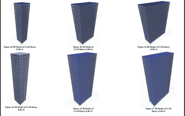
For the analysis, various models of RCC building with G+20 storey and G+30 storey were made with different aspect ratio. The aspect ratio was kept as 1,2 and 3 for wind load analysis.
1) Modelling Of G+20 Storey Unbraced Rcc Building
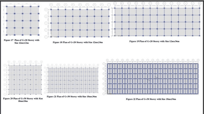
The G+20 storey RCC buildings were modelled for plan dimensions 12mx12m, 12mx24m and 12mx36m with the following beam and column sections.
Table- Column and Beam Sections used for design of G+20 RCC Building
|
Storeys |
Column Size(mm) |
Beam Size (mm) |
|
0-5 |
800x800 |
250x300 |
|
6-10 |
700x700 |
250x300 |
|
11-15 |
600x600 |
250x300 |
|
16-21 |
500x500 |
250x300 |
2) Modelling Of G+30 Storey Unbraced Rcc Building
The G+30 storey RCC buildings were modelled for plan dimensions 18mx18m, 18mx36m and 18mx54m with the following beam and column sections.
Table- Column and Beam Sections used for design of G+30 RCC Building
|
Storeys |
Column Size(mm) |
Beam Size (mm) |
|
0-10 |
900x900 |
250x300 |
|
11-20 |
800x800 |
250x300 |
|
21-31 |
700x700 |
250x300 |
D. Modelling Of Unbraced Steel Building
For design of steel buildings, built-up sections are used for columns. The section is made by one I Section and two T Section welded on its web. The section is named PLUSAXB where A is the depth of I section used and B is the thickness of plates. A typical cross section.For the flooring in steel building, we have used solid slab supported by secondary beams (ISLB 125, ISLB 150 and ISLB 175) due to composite action. The type of slab use is shown in the figure below, where h, the height of shear stud and t, is the thickness of concrete.
1) Modelling Of G+20 Storey Unbraced Steel Building
The G+20 storey Steel buildings with aspect ratio 1,2 and 3 were modelled with following sections.
Table - Steel Section used for Beam and Column for G+20 Steel Building
|
Storeys |
Column Size(mm) |
Beam Size (mm) |
|
0-5 |
PLUS600x16 |
ISHB300-2 |
|
6-10 |
PLUS500x16 |
ISHB300-2 |
|
11-15 |
PLUS400x16 |
ISHB300-2 |
|
16-21 |
PLUS400x25 |
ISHB300-2 |
2) Modelling Of G+30 Storey Unbraced Steel Building
The G+30 Steel buildings with aspect ratio 1.2 and 3 were designed with following sections.
Table 7 Steel Section used for Beam and Column for G+30 Steel Building
|
Storeys |
Column Size(mm) |
Beam Size (mm) |
|
0-10 |
PLUS600x25 |
ISHB300-2 |
|
11-20 |
PLUS500x25 |
ISHB300-2 |
|
21-31 |
PLUS400x25 |
ISHB300-2 |
E. Modelling Of Unbraced Steel Concrete Composite Building
The steel concrete composite building is designed with composite flooring system. The floor system used is profiled deck filled with concrete resting on ISLB 175. The column section used for composite building is concrete encased steel (CES) section, in which 1-Section is encased in concrete. In our design we have used ISMB section made of Fe250 Grade structural steel.
1) Modelling Of G+20 Storey Unbraced Steel Concrete Composite Building
The G+20 Composite buildings with aspect ratio 1,2 and 3 were designed with following sections.
Table - Composite Column Section and Steel Beam Section used for design of G+20 Steel Concrete Composite Building.
|
Storeys |
Column Size(mm) |
Beam Size (mm) |
|
0-5 |
650x650 with ISMB 500 |
ISHB300-2 |
|
6-10 |
550x550 with ISMB 400 |
ISHB300-2 |
|
11-15 |
450x450 with ISMB 300 |
ISHB300-2 |
|
16-21 |
350x350 with ISMB 200 |
ISHB300-2 |
2) Modelling Of G+30 Storey Unbraced Steel Concrete Composite Building
The G+30 Composite buildings with aspect ratio 1,2 and 3 were designed with following sections.
Table 10 Composite Column Section and Steel Beam Section used for design of G+30 Steel Concrete Composite Building.
|
Storeys |
Column Size(mm) |
Beam Size (mm) |
|
0-10 |
750x750 with ISMB 550 |
ISHB300-2 |
|
11-20 |
600x600 with ISMB 450 |
ISHB300-2 |
|
21-31 |
500x500 with ISMB 350 |
ISHB300-2 |
III. METHEDOLOGY
A. Arrangement Of Bracing System In Buildings
The buildings that were designed previously are now used to investigate the effect of bracings and aspect ratios, in onder to do so X. V. Inverted V and K bracings are applied on the tall buildings. K-bracing is generally discouraged in seismic regions because of the potential for column faikne if the compression brace buckles. The bays are braced from top to bottom ie, at each storey and are placed in the first and last hay. The building is braced at the corner inse it also reduces the twisting caused due to carthquake and wind loads. This is done by using Quick Add Bracings command of ETABS whete predefined bracing options are given for X, V and inverted V bracing. The K bracing has to he made by using add beams command as there is no predefined option available for it. Angle section is used for bracings in this study and ISA 150x150x10 is used for bracing. The bracing arrangement only for G-20 boilding with different aspect ratio.
B. Analysis of g+20 storey braced frames
This section shows the results of analysis obtained from the various models of RCC, Steel and Steel Concrete Composite Building with various aspect ratios and hracing systems. From the analysis fisun ETABS software the values of displacement at op Storey, sorey sdrift obtained at skorey 6 for G+20 storey due to wind loud in and the data of base shear and time period of structure due to earthquake load is ontained.
- Displacement Due To Wind Load In Y Direction: The value of displacement of top storey increases with increase in aspect ratin, the displacement in maximum for unbraced steel building as compared to its counterpart RCC and Composite building. The application of bracing system reduced the displacement considerably, thus increasing the stiffness of structure. The red line in Figure 32 shows that maximum allowable displacement of a building te., H/500. For G-20 storey Hof63m so maximum allowable displacement in 126mm.
- Displacement Due To Wind Load In X Direction: As per the Figure 33, as aspect ratio deflecion decreased considerably, this is due to the fact that stiffness of the system has been increased in this direction. The decrease in displacement due to the bracing system is considerable in building with L/B=1 but the reduction is less with increasing L/B ratio. The X bracing has caused the most redaction followed by inverted V bracing, K bracing and least by V bracing.
- Storey Drift Due To Wind Load In Y Direction: The storey drift in Y direction has increased with increase in aspect ratio, owing to the fact that more area of building has heen exposed to wind Irad. The trend remains the same as steel building has highest drift followed by composite and RCC hoilding. Reduction in drift due to bracing is maximum in L/B-1 and also due to X Bracing.
- Storey Drift Due To Wind Load In X Direction: The drift in X direction has reduced considerably with increase in L/B ratio, also the tracings have reduced the drift with maximum reduction due to X bracing.
- Base Shear Due To Earthquake Load In Y Direction: The base shear increases as the aspect ratio increases in all type of buildings. The base shear maximum for RCC building followed by composite building and least for steel buildings, With bracing system, the base shear tends to increase owing to the fact that stiffness of the building, is increased. Therefore, a building can catry large lateral louds with increase in aspect ratio and addition of bracing system.
- Base Shear Due To Earthquake Load In X Direction: In this case also base shear has increased with increase in L/B ratio as shown in figure 37 bat increment is more as compared to that in Y direction which is due to increased stiffness in X. direction a greater mumber of spans are present. The huse shear is minamum in Steel buikding and maximum for RCC Baskling
- Time Period Due To Earthquake Load In Y Direction: The time period of building increased with increase in aspect ratio, though it isn't significant. The bracing reduces the time period considerably owing to the fact that they increase the stiffness of system. The maximum reduction is in X hercings followed by Inverted V bacing.
- Time Period Due To Earthquake Load In X Direction: The time period decreases with increase in aspect ratio of the building, with lowest in case of L/B=3 for all buildings ive., RCC, Steel and Composite. The bracings have reduced the time period considerably for L/B-1 while reduction is quite less for L/B-2 and L/B-3.
C. Analysis Of G+30 Storey Braced Frames
In this section we see the results of analysis obtained from the various models of RCC, Steel and Steel Concrete Composite Building with various aspect ratios and bracing systems. From the analysis results obtained from ETABS software we have uken the values of displacement at top storey, storey drift obtained at storey 12 for G+30 storey due to wind load in X and Y direction. Also, we have obtained the data of base shear and time period of structure due to carthquake load in X and Y direction.
- Displacement Due To Wind Load In Y Direction: From the data obtained we can see that displacement in Y direction in the buildings increases as the aspect ratio is increased. The deflection of steel huildings is maximum as compared to its counterparts while RCC is minimam and that of composite lie hetween them. As the bracing systems are emploved, there is a reduction in displacement values. Here the red line shows the maximum allowable deflection of a building of height "II". For G+30 storey, height H=93m, therefore max deflection 186mm (H/500),
- Displacement Due To Wind Load In X Direction: From the above table we can see that as the aspect ratio increases, the displacement decreases in X direction, this could be due to increased stillness of the structure in that direction due to increase aspect ratio, Here also the trend remains the same, ie, steel with maximum deflection, RCC with minimum and Composite in herween them. The application of bracing system decreases the deflection in buildings with aspect ratio I only while in remaining, the mduction is very small. The red line denotes maximum deflection of 186mm.
- Storey Drift Due To Wind Load In Y Direction: The drift value obtained due to wind lead in Y direction are shown above. The wind load increases drift as aspect ratio increases, since more area is exposed to the wind force Similar to G-20, the drift decreases as bracing system is employed. As steel is most ductile, the drift is maximum, followed by composite and then with least value in RCC.
- Storey Drift Due To Wind Load In X Direction: As the aspect ratio increases, the drifi decreases considerably in X direction. The drift is still maximum for steel and manunum for RCC building. The bracings reduce the drift and i minimom for X Bracing.
- Base Shear Due To Earthquake Load In Y Direction: The hase shear also increases in G+ 30 building with increase in aspect emtio for all type of building. Being maximum for RCC building and minimum for steel building. The bracings increase the base shear in all models as they increase the stiffness of the structure and X bracings have shown maximam increase in hase shear as compared to other hracing systems.
- Base Shear Due To Earthquake Load In X Direction: The aspect ratio has increased the huse shear in all the buildings, but the have shear increment is more in X direction as compared to Y direction also the bracings have mercasol the value of base shear as in all models but the increased caused by X bracing is maximum. The increment isn't significant in building with L/B> 1.
- Time Period Due To Earthquake Load In Y Direction: The time period in G+30 buildings also with increase in L/B ratio but increase in not significant also the decrease in time period due to bracings isn't significant as well.
- Time Period Due To Earthquake Load In X Direction: The time period here decreases with increase in L/B ratio but not a significant reduction has been seen after increase from L/B-2 to L/B-3. Also, though bracings decrease the time. period but still it is evident from the data that the decrease is not considerable also the reduction also reduces as L/B ratio increases.
.
IV. RESULTS
A. comparative study of braced and unbraced buildings
In this chapter we will compare and discuss the results obtained from the analysis on ETABS software. The data acquired from analysis of models is represented graphically and the plots are studied in onfer to investigate the influence of aspect ratio and bracings systems on the parameters like top sanrey displacement, storey drift, base shear and time period of the system. The load acting in the direction longer side of the building is along X. Direction and lond acting in direction of shorter side of the building is along Y Direction. The combined plots of displacement, drift, base shear and time period for G+20 and G-30 building is shown below
B. Effect Of Aspect Ratio On Top Storey Displacement
The following section investigates the effect of aspect ratio on top storey displacement of G+20 storey and G-30 storey building due to wind load in X and Y direction. The data dbtained for the top storey uf various types of building is shown in the fonn of bar chiar and pacentage change with respect to L/B-1 is calculated and displayed in the form of tables.
1) Due To Wind Load In Y Direction
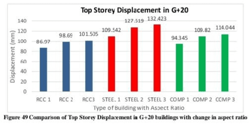
Table-Effect of Aspect Ratio on Top Storey Displacement in Y(G+20)
|
Types of Building |
RCC |
STEEL |
COMPOSITE |
|||
|
Aspect Ratio |
L/B=2 |
L/B=3 |
L/B=2 |
L/B=3 |
L/B=2 |
L/B=3 |
|
Increment (IN%) |
13.48 |
16.71 |
16.41 |
20.89 |
16.40 |
20.88 |
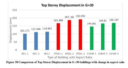
Table-Effect of Aspect Ratio on Top Storey Displacement in Y(G+30)
|
Types of Building |
RCC |
STEEL |
COMPOSITE |
|||
|
Aspect Ratio |
L/B=2 |
L/B=3 |
L/B=2 |
L/B=3 |
L/B=2 |
L/B=3 |
|
Increment (IN%) |
11.23 |
13.55 |
12.82 |
15.79 |
12.82 |
15.79 |
From figure 33 and figure 34 it can be seen that as the aspect ratio has been increased, the displacement has increased for all type of building. The percent increase in displacement is almost the same for steel and composite structure for a given aspect ratio but is more as RCC (3.23% for G+20 and 2.32% for G+30) as compared to Steel and Composite buildings (4.48% for G+20 and 2.97% for G+30). It is also observed that as the height of building increases, the percent increase in disolacement decreases slightly.
2) Due To Wind Load In X Direction
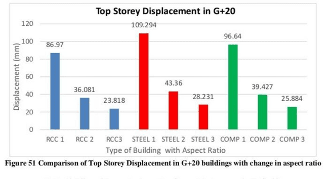
Table-Effect of Aspect Ratio on Top Storey Displacement in X(G+20)
|
Types of Building |
RCC |
STEEL |
COMPOSITE |
|||
|
Aspect Ratio |
L/B=2 |
L/B=3 |
L/B=2 |
L/B=3 |
L/B=2 |
L/B=3 |
|
Increment (IN%) |
58.51 |
72.61 |
60.33 |
74.17 |
59.20 |
73.22 |
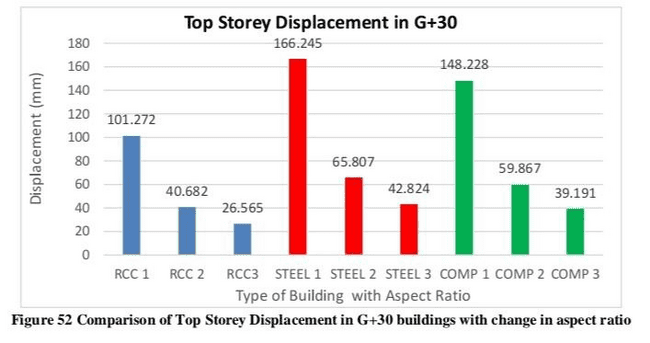
Table-Effect of Aspect Ratio on Top Storey Displacement in Y(G+30)
|
Types of Building |
RCC |
STEEL |
COMPOSITE |
|||
|
Aspect Ratio |
L/B=2 |
L/B=3 |
L/B=2 |
L/B=3 |
L/B=2 |
L/B=3 |
|
Increment (IN%) |
58.51 |
72.61 |
60.33 |
74.17 |
59.20 |
73.22 |
From table figure 51 and figure 52 it is observed that with increase in aspect ratio, the displacement is reduced for all type of building. All types of building experience reduction in displacement due increase in aspect ratio and the reduction is found out to be around 58%,61% for all types of building with L/B=2 and 72%-75% for all type of building with L/B=3, and this has no influence of height of building on it.
C. Effect Of Aspect Ratio On Storey Drift
In this section the influence of aspect ratio on storey drift on various types of buildings i.e.,RCC, Steel and Steel Concrete Composite is discussed. The data obtained for G+20 storey and G+30 storey building is plotted in the form of bar charts and it the increment/reduction of it w.r.t. L/B=1 is calculated. The comparisons are made in order to find meaningful results.
1) Due To Wind Load In Y Direction
Table-Effect of Aspect Ratio on Storey Drift in Y(G+20)
|
Types of Building |
RCC |
STEEL |
COMPOSITE |
|||
|
Aspect Ratio |
L/B=2 |
L/B=3 |
L/B=2 |
L/B=3 |
L/B=2 |
L/B=3 |
|
Increment (IN%) |
13.41 |
16.62 |
16.39 |
20,85 |
16.38 |
20.84 |
Table-Effect of Aspect Ratio on Storey Drift in Y(G+30)
|
Types of Building |
RCC |
STEEL |
COMPOSITE |
|||
|
Aspect Ratio |
L/B=2 |
L/B=3 |
L/B=2 |
L/B=3 |
L/B=2 |
L/B=3 |
|
Increment (IN%) |
11.27 |
13.58 |
12.78 |
15.78 |
12.82 |
15.77 |
After comparing data from above tables and figures, it can be seen that maximum drift value has been increased with increase in L/B ratio. The increment is slightly more in G+20 buildings as compared to G + 30 buildings. Also, the increment in Steel and Composite building (which is similar) is more than RCC building.
2) Due To Wind Load In X Direction
Table-Effect of Aspect Ratio on Storey Drift in X(G+20)
|
Types of Building |
RCC |
STEEL |
COMPOSITE |
|||
|
Aspect Ratio |
L/B=2 |
L/B=3 |
L/B=2 |
L/B=3 |
L/B=2 |
L/B=3 |
|
Increment (IN%) |
57.13 |
71.40 |
58.56 |
72.63 |
57.85 |
72.06 |
Table-Effect of Aspect Ratio on Storey Drift in X(G+30)
|
Types of Building |
RCC |
STEEL |
COMPOSITE |
|||
|
Aspect Ratio |
L/B=2 |
L/B=3 |
L/B=2 |
L/B=3 |
L/B=2 |
L/B=3 |
|
Increment (IN%) |
58.96 |
73.03 |
59.57 |
73.50 |
58.88 |
72.90 |
Due to wind load in X direction, there is a considerable decrease in maximum drift values with increase in L/B ratios. The reduction is quite same G + 20 or G + 30 buildings as well as for different type of building, which is evident from the data that reduction for L / B = 2 is between 57%-60% and for L / B = 3 is between 71%-74%. Though reduction is quite more in G + 30 buildings.
D. Effect Of Aspect Ratio On Base Shear
The following section investigates the effect of aspect ratio on base shear. The aspect ratio is kept as 1,2 and 3 for this study. The values obtained from the analysis is displayed in the form of bar charts and the increment w.r.t. L / B - 1 is calculated in the table. The data is compared and following insights are gained.
1) Due To Earthquake Load In Y Direction
Table-Effect of Aspect Ratio on Base Shear in Y(G+20)
|
Types of Building |
RCC |
STEEL |
COMPOSITE |
|||
|
Aspect Ratio |
L/B=2 |
L/B=3 |
L/B=2 |
L/B=3 |
L/B=2 |
L/B=3 |
|
Increment (IN%) |
87.70 |
175.39 |
86.29 |
172.77 |
83.87 |
167.71 |
Table-Effect of Aspect Ratio on Base Shear in Y(G+30)
|
Types of Building |
RCC |
STEEL |
COMPOSITE |
|||
|
Aspect Ratio |
L/B=2 |
L/B=3 |
L/B=2 |
L/B=3 |
L/B=2 |
L/B=3 |
|
Increment (IN%) |
89.03 |
178.07 |
89.75 |
179.47 |
88.24 |
176.47 |
From the table 19 and 20 we can infer that base shear has increased considerably with increase in L/B ratio. The base shear increment for G+20 and G+30 building for a particular L/B ratio is approximately same for RCC and Steel building and is more than that of Composite building. With increase in height of the building, the base shear increment for a particular L/B ratio has also increased slightly.
2) Due To Earthquake Load In X Direction
Table-Effect of Aspect Ratio on Base Shear in X(G+20)
|
Types of Building |
RCC |
STEEL |
COMPOSITE |
|||
|
Aspect Ratio |
L/B=2 |
L/B=3 |
L/B=2 |
L/B=3 |
L/B=2 |
L/B=3 |
|
Increment (IN%) |
91.73 |
184.33 |
102.22 |
204.40 |
102.34 |
201.76 |
Table-Effect of Aspect Ratio on Base Shear in Y(G+30)
|
Types of Building |
RCC |
STEEL |
COMPOSITE |
|||
|
Aspect Ratio |
L/B=2 |
L/B=3 |
L/B=2 |
L/B=3 |
L/B=2 |
L/B=3 |
|
Increment (IN%) |
99.74 |
199.21 |
102.93 |
205.55 |
99.43 |
198.61 |
For earthquake load in X direction, the base shear value has nearly doubled and tripled for I / B = 2 and L / B = 3 respectively for both G + 20 and G+30 building, though the increment in G+30 is more than G+20 as shown in Table 21 and Table 22. The Base Shear has increased with height for all buildings and similar to previous trends, the base shear for RCC is maximum out of all for G+20 and G + 30 buil?ing.
E. Effect Of Aspect Ratio On Time Period
The effect of aspect ratio on time period is studied in this section by plotting the data obtained from ETABS and calculated increment/reduction in the values is shown in the tables. The data obtained is from G+20 storey and G+30 storey building made of RCC, Steel and Steel Concrete Composite.
1) Due To Earthquake Load In Y Direction
Table-Effect of Aspect Ratio on Time Period in Y(G+20)
|
Types of Building |
RCC |
STEEL |
COMPOSITE |
|||
|
Aspect Ratio |
L/B=2 |
L/B=3 |
L/B=2 |
L/B=3 |
L/B=2 |
L/B=3 |
|
Increment (IN%) |
1.20 |
1.69 |
3.91 |
5.48 |
3.25 |
4.52 |
Table-Effect of Aspect Ratio on Time Period in Y(G+30)
|
Types of Building |
RCC |
STEEL |
COMPOSITE |
|||
|
Aspect Ratio |
L/B=2 |
L/B=3 |
L/B=2 |
L/B=3 |
L/B=2 |
L/B=3 |
|
Increment (IN%) |
0.69 |
0.93 |
2.39 |
3.24 |
1.9 |
2.58 |
Due to earthquake load in Y direction, the time period of building has increased with increase in aspect ratio. The time period for RCC buildings tend to be higher than other two types of building with lowest time period for Steel buildings. The increment on time period with aspect ratio is higher for G+20 building as compared to G+30 building as shown in table 23 and 24.
2) Due To Earthquake Load In X Direction
Table-Effect of Aspect Ratio on Time Period in X(G+20)
|
Types of Building |
RCC |
STEEL |
COMPOSITE |
|||
|
Aspect Ratio |
L/B=2 |
L/B=3 |
L/B=2 |
L/B=3 |
L/B=2 |
L/B=3 |
|
Increment (IN%) |
3.57 |
4.73 |
4.29 |
5.49 |
3.70 |
4.84 |
Table-Effect of Aspect Ratio on Time Period in X(G+30)
|
Types of Building |
RCC |
STEEL |
COMPOSITE |
|||
|
Aspect Ratio |
L/B=2 |
L/B=3 |
L/B=2 |
L/B=3 |
L/B=2 |
L/B=3 |
|
Increment (IN%) |
4.71 |
6.20 |
4.25 |
5.54 |
3.81 |
5.03 |
For the case of earthquake load in X direction, the time period decreases with increase in L/B ratio. The reduction for a type of building with highest and lowest time period remains the same as that of in Y direction. The reduction is more in G+30 huilding as compared to G+20 building for a same type and same L/B ratio. Thus, as the height increases the time period increases.
F. Effect Of Bracings On Displacement
In this section the data obtained from analysis of G+20 storey and G+30 storey is compiled in order to study the effects of bracings on top storey displacement due to wind load in X and Y directions.
1) Due To Wind Load In Y Direction
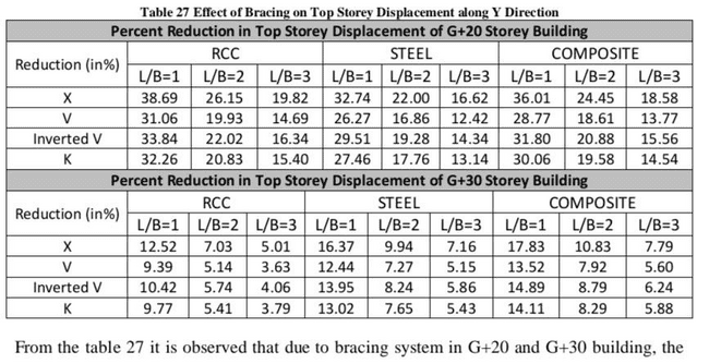
From the table 27 it is observed that due to bracing system in G + 20 and G+30 building, the displacement has been reduced. The reduction is maximum in X bracing in all cases, followed by inverted V. and K bracing. It is found to be least in V bracing. As the L/B ratio increases, the reduction in displacement decreases. It has been observed that the value of percentage reduction in L / B = 3 becomes less than half of that in L / B = 1 As the height of building increases, the reduction in displacement caused by bracings reduces, as it is evident that for G+20 R.C.C (L / B = 1) percent reduction is 38.69% while for same aspect ratio in G+30 RCC building it is 12.52%, which implies that current arrangement will not be effective in reducing displacement of G + 30 building. Also, as the L/B ratio increases in G+30 buildings, the reduction becomes very small e ., < 10%
2) Due To Wind Load In X Direction
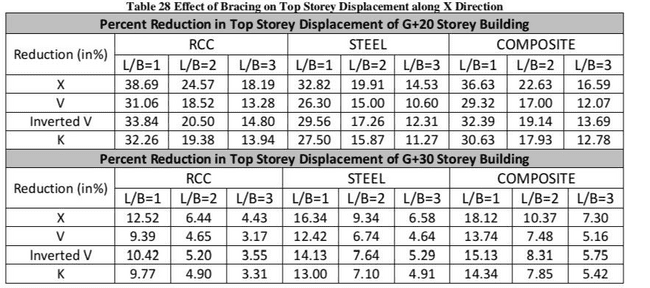
Due to bracings, the reduction is displacement has been observed in all types of buildings with different bracing system. From the Table 28, it is evident that in this case also, X bracing has caused most reduction in the displacement. And inverted V has caused second highest reduction. With increase in height of the building, the percent reduction in displacement has reduced, with maximum reduction observed in RCC building. V bracing has been found out to be least effective. With increase in aspect ratio there is a decrease in percent reduction of displacement, which means effectiveness of bracings reduces with increase in aspect ratio. The bracings have reduced the displacement in X and Y direction almost by the same amount when compared for the same building, though reduction is marginally more in Y direction. Here also for G + 30 building the reduction in displacement in X and Y direction is maximum for Composite building on contrary to G+20 building where reduction was between that of RCC and Steel. From this we can say that with increase in height, composite buildings with bracings show more reduction in displacement.
G. Effect Of Bracings On Drift
The storey drift to due to wind load is used to study the effect of bracings by observing the changes in the values of drift after addition of bracings in the structure. The load is applied along the width (Y direction) and along the length (X direction) of the building.
1) Due To Wind Load In Y Direction
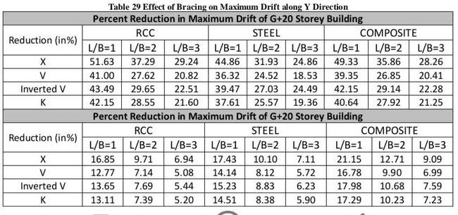
The bracing has reduced the drift on G + 20 building considerably. Table 29 showed that the maximum reduction is in R.C.C building. The reduction is less in G + 30 building as compared to G + 20 building from which we can infer that with increase in height, the provided bracing arrangement's efficacy has been reduced. The X bracing is most effective in reducing the drift followed by inverted V. K and V bracing. With increase in aspect ratio there is a decrease in percent reduction of drift, which means effectiveness of bracings reduces with increase in aspect ratio.
2) Due To Wind Load In X Direction
It can be observed from Table 30 that there is a reduction in drift due to bracings. In this case also, with increase in height of building the percent reduction decreases for the building with same type and L/B ratio. X bracing has reduced the drift more than any other bracing. The trend for effectiveness of bracing remains the same. The bracings have reduced the drift in X and Y direction almost by the same amount when compared for the same building, though reduction is marginally more in Y direction.
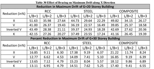
For G + 30 building the reduction in drift in X and Y direction is maximum for Composite building on contrary to G+20 building where reduction was between that of RCC and Steel. From this we can say that with increase in height, composite buildings with bracings show more reduction in drift.
H. Effect Of Bracings On Base Shear
1) Due To Earthquake Load In Y Direction
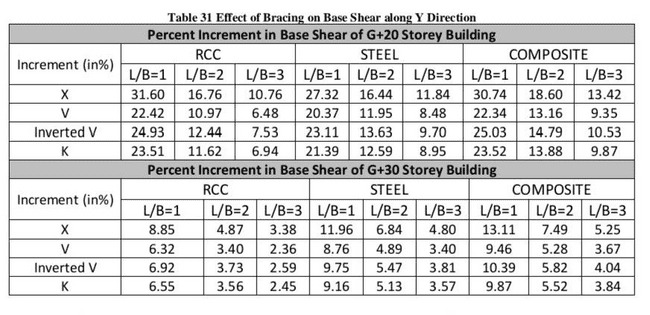
With addition of bracing system in buildings, there has been a slight increase in base shear due to earthquake load in Y direction. Table 31 shows that increment is more in G+20 building as compared to G + 30 building, where there is a slight increment. The X bracings has caused the most increment in base shear as compared to other bracing types. With increase in height as well as aspect ratio for a particular type of building, there has been a reduction in percent increment in base shear. For G + 30 building with increase in L/B ratio the increase in base shear becomes very small <5%.
2) Due To Earthquake Load In X Direction
With addition of bracing system in buildings, there has been a slight increase in base shear due to earthquake load in Y direction. Table 31 shows that increment is more in G+20 building as compared to G + 30 building, where there is a slight increment. The X bracings has caused the most increment in base shear as compared to other bracing types. With increase in height as well as aspect ratio for a particular type of building, there has been a reduction in percent increment in base shear. For G + 30 building with increase in L/B ratio the increase in base shear becomes very small <5%.
3) Due To Earthquake Load In X Direction
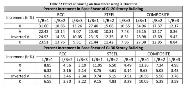
As per Table 32 there has been only a slight increase in base shear for G+30 building while it is quite more for G + 20 building showing the effects of height on bracing system. With increase in aspect ratio, the increase in base shear tends to decrease. X bracing shows most increment in base shear for all type of building. Also, for G + 30 building the increment in base shear is maximum for Composite building on contrary to G+20 building where in height, composite buildings with bracings show more increment in base shear.
I. Effect Of Bracings On Time Period
1) Due To Earthquake Load In Y Direction
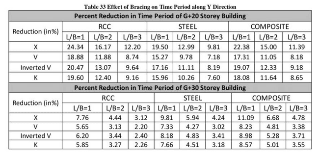
The bracings have reduced the time period of all the buildings. In case of G / 20 building the reduction is more as compared to that in G + 30 building as observed from Table 33. The X bracings have caused the most reduction in time period. In G+30 buildings reduction in very small and as aspect ratio increases, the reduction caused by other bracings becomes more or less the same. In G / 20 even when the aspect ratio is increased, the reduction is still more than that of G + 30 building and is quite distinct for each type of bracing. The reduction is highest in composite building for G+30 in comparison to G+20 building.
2) Due To Earthquake Load In X Direction
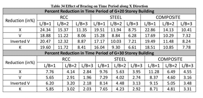
There has been reduction in time period due to bracings in building but it is more in G + 20 as compared to G+30. The reduction in G + 30 tends to become negligible as the aspect ratio is increased and is very much less in comparison to G + 20 as shown in Table 34. Composite building still has the most reduction in G+30. X bracing has caused most reduction in all buildings.
Conclusion
In the present study various models of RCC, Steel and Steel Concrete Composite buildings were analyzed using ETABS software in order to study the wind response of G+20 storey and G+30 storey building with various aspect ratio and bracing system. Three different aspect ratios were considered and four types of bracing systems were used to investigate the wind response in terms of top storey displacement and maximum drift due to wind load. The seismic response was also studied in terms of base shear and time period of the building. The investigation has shown that aspect ratio and bracing system greatly affects the wind response of tall buildings. From the present study, the following conclusions can be drawn 1) The aspect ratio predominant parameter to influence the wind and seismic respinse of a tall building. The displacement, drifi, base shear and time period response increase along the width and they decrease along the length of a building when the aspect ratio is increased. 2) The response depends on different type of construction ie, RCC, Steel and Steel Concrete Composite. The storey displacement, drift and time period was least for RCC building as compared to the Steel buildings, while Base Shear was maximum for RCC and minimum for Steel building. 3) Adding of bracings system in a building, there has been a signifikant change in the response of buildings. The result showed that X bracing was most effective among all bracings in reducing the displacement, drifi and time period and increasing the base shear of the building. Whereas, Inverted-V bracing is less effective than X bracing but more effective than remaining two bracings (K and V bracing). From the analysis it is found that K bracing was less efficient than inverted V bracing but more efficient than V bracing. V bracing is found to be the least efficient. 4) The efficiency of bracing system is found to be reduced with increase in height of the building and also with the increase in aspect ratio of the building. Though the efficiency of the bracings reduced with height for RCC, Steel and Steel Concrete Composite building but they become most efficient for Steel Concrete Composite buildings with increase in height.
References
[1] Abhas H.S.. Khamooh M.M., Atia N.S. and Bassam F.R. (2022) Analysis or Design of Composite Column hy Using ETABS Software Webology 19(1), pp.5289-5301. Available at: https://doi.org/10.14704/web/19il/web19355: [2] Rana S. Das S., Kumar V. Raj R (2022) Comparison Study of Responses Generated In Rectangular and Octagonal Shaped High Rise Buildings under Wind Loads\". Article in International Journal of Research in Engineering and Technology [Preprint) Volume: 09 Issue: 04. Available at: https://www.researchgate.net/publication/360602023. [3] Venna, B. Baghel B., Chakrallhari A. and Agrawal A. (2022) Analysis of Wind Load Tall Building of Various Aspect Ratios Available https://www.researchgate.net/puhlication/357876749, [4] Lateef Najar, M.A. et al. (2021) Earthquake Analysis of Multistoried Residential Building, International Journal of Innovative Research in Science, Engineering and Technology, 10(6). Available at:https://doi.org/10.15680/JIRSET 2021.1006126. [5] Sothar, N. And Goyal, P.K. (2021) Comparison of response of huilding against wind load as per wind codes [IS 875 (Part 3) 1987] and [15 875 (Part 3) 2015, in IOP Conference Series: Earth and Environmental Science. IOP Publishing Ltd. Available https://doi.org/10.1088/1755-1315/796/1/112007 [6] Darwish, A. Q.(2000) \'A Review on Steel Concrete Composite Structures\", International Research Joumal of Engineering and Technology [Preprint]. Available www.steelconstruction.info%2fcomposite construction&ips. [7] Patel, R. and Meglina (2020) \'A Review on Comparative Study of K Bracing System and X Bracing System for RC Frame Smictures, International Research Joumal of Engineering and Technology (Preprint). Available at www.irjet.net. . [8] Agarwal, N. And Garg, N. (2018) \'A Research on Study and Analysis Of Multi-Storey 8 Steel Building Using E-Tab Software, IJIRMPS, 6. [9] Aswathi P. M., N.N.M. Enisal, T Fasna, Mahmood, EL, Muhan?mad and B. Sivakumar (2018) Seismic Comparison of OMRE and SMRF Structural Systems on High Rise Building, SSRG International Journal of Civil Engineering (SSRG-IICI)-volume 5 Issue 5 Available at www.internationaljournalisrg.org [10] Kandpal U (2018) \"Comparative Analysis of Rectangular and square colunm for Axial loading, Uniaxial & Hiaxial Bending\", International Research Journal of Engineering and Technology (IRJET), 05(02), pp. 465-468. [11] Sachin, S. (2018) \"Study of Seismic Behavior on Multi Storied Buiklings with Composite Columns, International Journal for Research in Applied Science and Engineering. Technology, Vol. 6 Issue 4, Available at: http://doi.org/10.22214/jraset. 2018.4783, [12] Jadhav G.S Sutar S.R. und Bankar S.V. (2017) Comparative Analysis of RCC And Steel-Concrete Composite Multistoried Building, kornal Of Information, Knowledge and Research in Civil Engineering, Volume 4, Issue 2. [13] Kumar Baswa S., Patnaikuni K., Babu A. and K.V.G.D. Balaji, (2017), Effect of Steel Bracings on RCC Framed Structure. International Journal of Mechanics and Solids.Volume 9, Number 1, pp. 97-112 [14] Dammam, V.S. (2016) \"Design of Steel Concrete Composite Structure as Comparative with Reinforced Concrete Structure by Adapting Stand. Provki, Intanational Journal of Engineering Sciences & Management Research. 15. Available https://doi.org/10.13140/RG.2.2.1212541442 [15] Sadh, S.K. and Pendharkar, U. (2016) Influence of Aspect Ratio & Plan Configurations on Seismic Performance of Multitoried Regular RCC Buildings: An Evaluation by Response Spectrum Analysis\", International Research Journal of Engineering and Technology [Preprint). Available at: www.irjet.net. [16] Tanawade S. B. Kore P.N., Swami P.S. and Javheri S.B. (2016) \'Seismic Response of Reinforced Concrete Concentrically A-Braced Frames, International Journal of Innovation in Engineering, Research and Technology [IHERT] [Preprint]. [17] Aska B R and Sowjanya, G.V. (2015) Comparison of Seismic Behavior of a Typical Multi-Storey Structure with Composite Columns and Steel Colunas, International Journal of Civil and Structural Engineering Research. Available at www.researchpublish.com. [18] Zaveri, P.K., Desai, A.N. and Agrawal, V. V (2015) Electiveness of Steel Bracing Systems. Available at: https://www.researchgate.net/publication/314183463. [19] Ambadkar, S.D. and Pajgade, P.S. (2012) \"Design of Steel Frame Industrial Building Compared with Reinforced Cement Concrete Inchustrial Building, International Joumal of Scientific & Engineering Research, 3(6). Available at: http://www.ijser.org. [20] Patil, M.N. (2007) Composite Column-Importance and Design Methodology as perIndian Code, International Journal of Innovative Research in Science, Engineering und Technology, Vol. 6 Issue 1. Available at hups://doi.org/10.15680/IRSET 2017.0601098 [21] IS 875:2015, \"Design Loads (Other than Earthquake) for Building and Structures - Code of Practice (Part 3 Wind Load) Borcau of Indian Standards (BIS), Indias [22] IS 1893(Part 11:2016. \"Cinteria for Earthquake Resistant Design of Structures Part 1 General Provisions and Buildings.\" Bureau of Indian Standards (BIS), India [23] IS 456:2000, \"Plain and Reinforced Concrete Code of Practice\", Bureau of todian Standards (BIS), India. [24] IS 800:2007, \"General Construction in Steel Code of Practice\", Bureau of Indian Standands (BIS), India.
Copyright
Copyright © 2024 Mamta ., Vijay Kumar, Pradeep Kumar Nirmal, Anita Chaturvedi. This is an open access article distributed under the Creative Commons Attribution License, which permits unrestricted use, distribution, and reproduction in any medium, provided the original work is properly cited.

Download Paper
Paper Id : IJRASET64765
Publish Date : 2024-10-23
ISSN : 2321-9653
Publisher Name : IJRASET
DOI Link : Click Here
 Submit Paper Online

