Ijraset Journal For Research in Applied Science and Engineering Technology
- Home / Ijraset
- On This Page
- Abstract
- Introduction
- Conclusion
- References
- Copyright
Wireless Power Transfer of Electric Vehicle Battery Charging
Authors: Prof. S. K. Mude, Vishal Sahare, Siddharth Waghmare, Chetan Kosre, Lekhraj Hedaoo
DOI Link: https://doi.org/10.22214/ijraset.2024.61711
Certificate: View Certificate
Abstract
Wireless power transfer (WPT) is a cutting-edge technology that utilizes magnetic resonance to eliminate the need for cumbersome wires. WPT builds upon the principles of inductive power transfer and has been rapidly advancing in recent years. At power levels of kilowatts, the transfer distance can range from a few millimeters to several hundred meters, achieving an efficiency of over 90%. This progress has made WPT an attractive option for electric vehicle (EV) charging, both in stationary and dynamic settings. This study examines the latest developments in WPT as it pertains to wireless charging for EVs. By integrating WPT into EVs, challenges such as charging time, range, and cost can be effectively addressed. Battery technology is no longer a limiting factor in widespread adoption, and it is hoped that researchers will be inspired by recent advancements to further enhance WPT and expand the use of EVs.
Introduction
I. INTRODUCTION
Every conventional vehicle is solely powered by an internal combustion engine (ICE). These traditional vehicles emit harmful exhaust gases during operation, which can be detrimental to human health. However, electric vehicles (EVs) operate solely on electricity. They are propelled by one or more electric motors that are powered by rechargeable battery packs. As a result, electric vehicles offer several advantages over conventional vehicles. They do not emit harmful gases, their fuel costs can be up to 70% lower than those of conventional vehicles, and their maintenance costs are also lower. Additionally, electric vehicles are ideal for stop-and-go city driving as they do not consume energy when stationary. However, despite these benefits, electric vehicles have some drawbacks. The initial cost of purchasing an electric vehicle is high, and the charging time for EV batteries is longer compared to refueling a gas-powered vehicle. It takes approximately thirty minutes to several hours to fully charge an electric vehicle, depending on the power level of the charger. Furthermore, electric vehicles cannot be immediately recharged once their batteries are depleted. This means that owners must find a suitable opportunity to plug in and charge their batteries. This can be inconvenient as people may forget to plug in their vehicles and end up with no battery power later on. Additionally, charging cables on the ground can pose tripping hazards, and damaged cables can create dangerous conditions, especially in cold areas. Moreover, individuals may have to contend with adverse weather conditions such as wind, rain, ice, or snow when plugging in their vehicles, increasing the risk of electric shock. Therefore, the wireless power transfer (WPT) technology, which eliminates all the charging inconveniences, is highly desirable for EV owners. With wireless charging, the charging process becomes the easiest task. For a stationary WPT system, drivers simply need to park their vehicles and leave. Furthermore, EVs with wireless charging can have reduced battery capacity of 20% or less compared to EVs with conductive charging. The development of wireless charging technology.
II. ELECTRIC VEHICLE
Electric vehicles utilize a simple form of self-propelled mechanical transport. The drive train consists of a battery array connected to an electric motor through a switch. The electric motor is controlled to efficiently drive the wheels by regulating the amount of electricity passing through.
A. Electric Motor
The vehicle can be powered by AC or DC motors. DC motors operate within a voltage range of 96V to 192V with a power rating of around 20kW. These motors function based on electromagnetic induction, causing the central shaft to rotate due to changes in magnetic flux. On the other hand, AC motors typically run on 220-240 Volts AC with 300 Volt battery packs. AC motors come in various sizes, shapes, and power ratings, unlike DC motors, and offer a 'regenerative braking' feature where the motor can charge the batteries while braking.
B. Motor Controller
The motor controller regulates the current supplied to the motor based on the pressure applied to the accelerator pedal. Potentiometers connected to the accelerator act as variable resistors to determine the power delivery. When the accelerator is not pressed, no power is delivered, and full power is supplied when the pedal is fully pressed. For DC motors, the controller adjusts the DC supply voltage to produce a current proportional to the pressure on the accelerator.
C. Batteries
Car batteries are essential components that store energy for the vehicle's operation. They hold chemical energy and convert it into electrical energy when needed. Despite being heavy, bulky, and slow to charge, they have limited capacity and lifespan. LiMH batteries are superior alternatives, doubling the car's range and lasting longer, but they are currently too costly to consider. Fuel cells provide a promising solution, being eco-friendly and efficient, but further research and development are necessary before they become widely available.
III. WIRELESS POWER TRANSFER SYSTEM FOR ELECTRIC VEHICLE
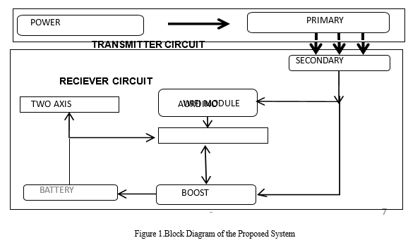
The block diagram shown in Figure 1 illustrates the proposed wireless power supply system for charging the battery of an electric vehicle. It comprises a transmitter for generating an AC signal to be transferred, transmitting and receiving coils for wireless power transfer, and a receiver to convert the received AC signal into DC voltage for battery charging. Through mutual induction, the primary and secondary coils are coupled, allowing the transfer of charge to the receiving circuit and storage in the battery.
A. Microcontroller
A microcontroller is a compact computer integrated circuit that includes a processor core, memory, and programmable input/output peripherals. Program memory, such as Ferroelectric RAM, NOR flash, or OTP ROM, is commonly found on the chip, along with a small amount of RAM. Microcontrollers are specifically designed for embedded applications, unlike the microprocessors found in personal computers or general-purpose devices. They are utilized in products like automobile engine control systems, medical implants, remote controls, office equipment, power tools, toys, and various embedded systems. By integrating the functions of a microprocessor, memory, and input/output devices into a single chip, microcontrollers help reduce size and cost, making it feasible to digitally control a wide range of devices and processes.

B. DC To DC Converter
A rectifier is a circuit that changes an AC signal to DC. It is constructed using diodes. Rectifiers have various applications, but are commonly utilized as a component in DC power supplies and high-voltage direct current power transmission systems. The bridge rectifier is offered in different packages, ranging from a few amperes to several hundred amperes. In bridge rectifier circuits, a semiconductor diode is typically employed to convert AC, as it permits current flow in only one direction (unidirectional device).
C. Boost Converter
A boost converter is a type of switched-mode power supply that can serve multiple purposes, including functioning as a DC to DC converter with an output voltage higher than the input voltage. A boost converter is sometimes referred to as a step-up converter. Since power (P=VI) must be conserved, the output current is lower than the input current. Often, even if a DC power source, such as a battery, is available, its voltage may not be suitable for the system it is intended to power. For instance, electric vehicle motors require significantly higher voltages, around 500V, than what a single battery can provide. Even if multiple batteries were used, the added weight and space required would make it impractical.
IV. RESONANT INDUCTIVE COUPLING
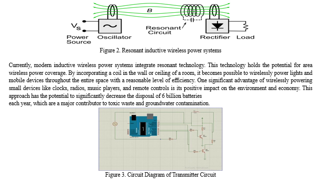
Resonant inductive coupling involves the transfer of power through magnetic fields between two resonant circuits, one in the transmitter and one in the receiver. Each circuit comprises a coil of wire connected to a capacitor or a self-resonant coil, or another resonator with internal capacitance. These circuits are tuned to resonate at the same frequency, enhancing coupling and power transfer. The principle is similar to how a vibrating tuning fork can induce sympathetic vibration in another fork tuned to the same pitch. Resonant inductive coupling relies on high Q factor resonators that exchange energy more efficiently than they lose it due to internal damping. This allows for power transfer over greater distances using weaker magnetic fields in the peripheral regions of the near fields. Efficiency can be achieved at ranges 4 to 10 times the coil diameter, known as "mid-range" transfer. In contrast, non-resonant inductive transfer is considered "short range" and requires adjacent coils for similar efficiency. Resonant circuits interact more strongly with each other than with non-resonant objects, minimizing power losses due to absorption in nearby stray objects. However, a drawback of resonant coupling is that at close ranges, the resonant frequency splits into two peaks, requiring tuning of the oscillator frequency for maximum power transfer.

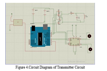
The power supply circuit on the primary side is responsible for transferring energy wirelessly through the coil. It comprises a step-down transformer connected to a rectifier circuit. This setup is designed to charge a 12v battery by stepping down the 230v AC voltage to 12v AC. Consequently, the battery stores energy in the form of DC only. To achieve this, the rectifying circuit rectifies the 12v AC supply to 12v DC, as illustrated in figure 3. The rectified DC then flows through the inductive coil via transistor. The transistor's frequent switching generates a strong magnetic field in the primary coil, providing power supply to the secondary circuit. This enables the transfer of charge to the secondary side wirelessly.
A. Receiver Circuit
The receiver circuit is responsible for managing the charging system of the battery, which serves as the main power source for the electric vehicle. It is composed of a copper coil with a specific number of turns that can be positioned on the conducting material of the primary circuit. The energy transmitted wirelessly is rectified by the rectifier, with the battery storing the energy in DC form only, as illustrated in figure 4. However, the rectified DC alone is not sufficient to efficiently charge the battery, so the controller design plays a crucial role in storing the energy effectively. The controller references the DC voltage to generate the necessary pulses for the booster circuit.

Conclusion
EVWC technology is experiencing rapid growth and progress. As the EV market gradually expands, charging systems are becoming commercially available, and the improved infrastructure is expected to enhance the popularity of EVs. Ongoing advancements are enhancing the efficiency of EVWC, leading to intense competition among various players in this emerging market niche. It is worth noting that wireless charging can be just as efficient as wired charging. Based on the analysis of literature and collected data, it is suggested that wireless power transmission is a feasible option. Thanks to modern science, it is now possible to utilize electricity for charging without the need for wired connections. There are three techniques available for wireless power transfer. Inductive charging, although less efficient and prone to increased resistive heating compared to direct contact, is one of these techniques. Implementations that employ lower frequencies or older drive technologies result in slower charging and generate heat within most portable electronics. Magnetic microwave charging also has limitations, such as signal absorption by the atmosphere and attenuation due to atmospheric conditions, as well as the high cost of building towers. However, researchers have developed inductive charging using resonance, where energy is transmitted between two copper coils that resonate at the same frequency. One coil serves as the power transmitter, while the other acts as the receiver. This technique is considered more feasible than others and is also safer than wired charging systems. In this particular project, the focus has been on wireless charging of a 1050mAh battery. The circuit for this purpose has been designed, fabricated, implemented, and tested.
References
[1] Chun Qiu, K.T. Chau “Overview of Wireless power transfer (WPT) for Electric Vehicle Charging” IEEE Trans Ind. Electron, Jan 2013. [2] Cheon S et al.: “Circuit-model-based analysis of a wireless energy-transfer system via coupled magnetic resonance. IEEE Trans. Ind. Electron (2012) [3] Zhu Han “Wireless Charging Technologies: Fundamentals Standards and Network Applications” Department of Electrical and Computer Engineering University of Houston, November 2014. [4] J Gobinath, Vinoth M Kumar and M Lenin. Article: Short Range Wireless Charging System for Smart Phone through New Energy Harvesting Circuit. IJCA Proceedings on International Conference on Current Trends in Advanced Computing ICCTAC2014:1-5, May 2014. [5] S. R. Khutwad and S. Gaur, \"Wireless charging system for electric vehicle,\" 2016 International Conference on Signal Processing, Communication, Power and Embedded System (SCOPES), Paralakhemundi, 2016, pp. 441-445. [6] Lu, Xiao & Niyato, Dusit & Wang, Ping & In Kim, Dong & Han, Zhu. (2014). Wireless Charger Networking for Mobile Devices: Fundamentals, Standards, and Applications. Wireless Communications, IEEE. 22. 10.1109/MWC.2015.7096295. [7] X. Lu, P. Wang, D. Niyato, D. I. Kim and Z. Han, \"Wireless Charging Technologies: Fundamentals, Standards, and Network Applications,\" in IEEE Communications Surveys & Tutorials, vol. 18, no. 2, pp. 1413-1452, Second quarter 2016. [8] Hadley, Franklin (2007-06-07). \"Goodbye wires…\". MIT News. Massachusetts Institute of Technology. Retrieved 2007-08-23. the advance online publication of the journal Science. MIT team experimentally demonstrates inductive. [9] G. A. Covic and J. T. Boys, \"Modern Trends in Inductive Power Transfer for Transportation Applications,\" in IEEE Journal of Emerging and Selected Topics in Power Electronics, vol. 1, no. 1, pp. 28-41, March 2013. [10] Chang-Gyun Kim, Dong-Hyun Seo, Jung-Sik You, Jong-Hu Park and B. H. Cho, \"Design of a contactless battery charger for cellular phone,\" in IEEE Transactions on Industrial Electronics, vol. 48, no. 6, pp. 1238-1247, Dec. 2001. [11] H. Zhai, H. K. Pan, and M. Lu, \"A practical wireless charging system based on ultra-wideband retroreflective beamforming,\" presented at IEEE International Symposium on Antennas and Propagation, Toronto, Canada, July 2010. [12] L. Chiu, T. Y. Yum, W. S. Chang, Q. Xue, and C. H. Chan, \"Retrodirective array for RFID and microwave tracking beacon applications,\" Microwave and Optical Technology Letters, vol. 48, no. 2, pp. 409-411, February 2006. [13] B. Cannon, J.F. Hoburg, D.D. Sancil and S.C. Goldstein, “Magnetic resonant Coupling as a Potential Means for Wireless Power Transfer to Multiple Small Receivers”, IEEE Transactions on Power Electronics,vol.24, issue 7, July 2009, Page(s):1819-1825. [14] Wireless Power Consortium, “System description wireless power transfer” Vol.1, Part I, II and III
Copyright
Copyright © 2024 Prof. S. K. Mude, Vishal Sahare, Siddharth Waghmare, Chetan Kosre, Lekhraj Hedaoo. This is an open access article distributed under the Creative Commons Attribution License, which permits unrestricted use, distribution, and reproduction in any medium, provided the original work is properly cited.

Download Paper
Paper Id : IJRASET61711
Publish Date : 2024-05-06
ISSN : 2321-9653
Publisher Name : IJRASET
DOI Link : Click Here
 Submit Paper Online

